SignalFire RANGER Wall Mount User manual

1
Rev 1.1
RANGER Wall Mount Manual
The RANGER Wall Mount version is designed to allow for wall mount installations and to provide
environmental protection for the RANGER
-Dual digital inputs report state, total counts, and input frequency. K-Factor configurable for Flow
Totalizing
-SPDT Latching relay for local on/off control
-Configurable from the SignalFire Cloud website signal-fire.cloud
-SignalFire Cloud allows for data visualization, trending, and alarming
-Supports MQTT Sparkplug B communication protocol for connection to other servers
-Compact and simple to install and maintain
-Local configuration and diagnostics available using the micro-USB port and the SignalFire RANGER
ToolKit PC software
-Expansion modules for additional I/O (2AI/1DI, Modbus, HART, SDI-12)
-Internal backlog of a minimum of 200,000 datapoints in the event of loss of signal. Backlog will be
automatically sent when the RANGER reconnects
-Can be field converted to support an external antenna
-Class 1 Division 2 certified
SignalFire Telemetry

2
Rev 1.1
Specifications
Enclosure Size
Polycarbonate 7.8” tall × 8.27” wide x 4” deep
IP68 rated
2.1Lbs (1kg)
Power Source
Internal Lithium battery pack (SignalFire Part Number: 4DPak)
Optional solar or external DC power options also available
Temperature
Rating
RANGER SIM Slot
RANGER Local
config port
RANGER Analog
Input
RANGER Digital
Inputs
RANGER Relay
Output
RANGER Sensor
Power Output
-40°C to +85°C
4FF Nano SIM card (LTE Cat M SIM and data plan required)
Standard micro-USB connector
Provides 13Vdc/18Vdc, (selectable) to attached 4-20mA / 1-5Vdc sensor. One analog input
built in. Up to three with additional 2AI/1DI module.
Two digital inputs. Three with additional 2AI/1DI module. Dry Contact or 30 Volts Max
(push-pull), 2kHz max. Capable of reporting on state change
Latching Relay. 2A @ 30VDC, 0.3A @ 110VDC, 0.5A @ 125VAC
Selectable 13Vdc / 18Vdc. 60mA max power output
Compliance
•Contains FCC ID: 2ANPO00NRF9160 and IC ID: 24529-NRF9160
•PTCRB and Verizon Network Certified
•Certified for use in Class I, Division 2, Groups A, B, C, D areas. Temperature Code T5
EXi [EXi]
•[UL 121201:2017 Ed.9+R:26Aug2019], [CSA C22.2#213:2017 Ed.3+U1;U2]
•IEC 62638-1:2014 (2nd Ed), EN 62368-1:2014+A11:2017
3
Rev 1.1
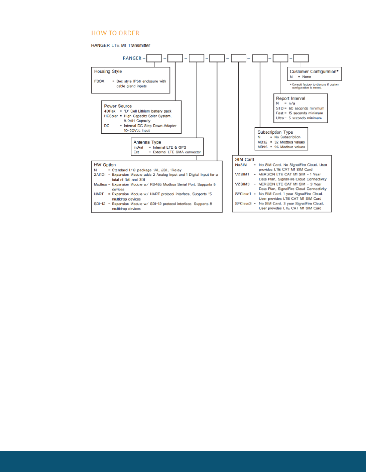
Model Numbers

4
Rev 1.1
Table of Contents
Specifications ..........................................................................................................................................................................2
Table of Contents....................................................................................................................................................................4
Hazardous Location Certification............................................................................................................................................5
Dimensions.............................................................................................................................................................................. 6
Connections and Components................................................................................................................................................7
Sensor Connections.................................................................................................................................................................8
Analog Input........................................................................................................................................................................ 8
Digital Inputs.......................................................................................................................................................................9
Relay Output .....................................................................................................................................................................10
2AI/1DI..............................................................................................................................................................................11
Modbus RS-485.................................................................................................................................................................12
HART..................................................................................................................................................................................13
SDI-12................................................................................................................................................................................14
RTD....................................................................................................................................................................................15
Power Options ......................................................................................................................................................................16
Lithium Battery Pack (4DPak)............................................................................................................................................16
DC-DC converter ...............................................................................................................................................................16
HC-Solar System................................................................................................................................................................16
Internal Lithium Battery Replacement..............................................................................................................................16
Mounting and Care ...............................................................................................................................................................17
External Antenna Conversion ...............................................................................................................................................18
Cloud Setup and Information................................................................................................................................................20
Technical Support and Contact Information.........................................................................................................................21
Revision History ....................................................................................................................................................................21

5
Rev 1.1
Hazardous Location Certification
The RANGER is rated Class 1 Division 2 non-incendive when powered by its internal battery pack.
or its internal DC-DC converter. The HCSolar unit is not C1D2 certified so it is for general purpose
areas only.
WARNING: EXPLOSION HAZARD. DO NOT REMOVE OR REPLACE COMPONENTS UNLESS
POWER HAS BEEN DISCONNECTED OR THE AREA IS FREE OF IGNITIBLE CONCENTRATIONS.
AVERTISSEMENT : RISQUE D'EXPLOSION . NE PAS RETIRER OU REMPLACER LES
COMPOSANTS QUE L’ALIMENTATION EST DÉBRANCHÉ OU ZONE EST LIBRE DE
CONCENTRATIONS IGNITIBLE.
WARNING – EXPLOSION HAZARD Substitution of components may impair
suitability for Class I, Division 2
AVERTISSEMENT - RISQUE D'EXPLOSION. La substitution de composants peut rendre ce
materiel inacceptable pour les emplacements de classe I, division 2
WARNING – EXPLOSION HAZARD Do not disconnect while circuit is live unless area
is known to be nonhazardous
AVERTISSEMENT - RISQUE D'EXPLOSION. Ne débranchez pas lorsque le circuit est en
direct , sauf si la zone est connue pour être nonhazardous
WARNING – All wiring methods must be in accordance with the NEC
AVERTISSEMENT - Toutes les méthodes de Essorez doivent être en conformité avec la NEC
WARNING - EXPLOSION HAZARD. Do no remove or replace while circuit is live
unless the area is free of ignitable concentrations.
AVERTISSEMENT - RISQUE D'EXPLOSION. Ne pas enlever ou remplacer pendant que le
circuit est vivant à moins que la zone soit exempt de concentrations ignitibles.
WARNING – EXPLOSION HAZARD. Do not remove or replace lamps, fuses, or plug-in
modules (as applicable) unless power has been disconnected or the area is free of
ignitable concentrations.
AVERTISSEMENT - RISQUE D'EXPLOSION. Ne retirez ni ne remplacez les lampes, les
fusibles ou les modules enfichables (le cas échéant) à moins que l'alimentation ait été
coupée ou que la zone soit exempte de concentrations inflammables.

6
Rev 1.1
Dimensions

7
Rev 1.1
Connections and Components
STATUS LED
-The STATUS LED (green) will flash 3 times on a successful data transmission to the server
ERROR LED
-The ERROR LED (red) will blink 3 times to indicate that an attempted data transmission failed
Check-in Button
-If this button is pressed the RANGER will blink the green or red status LED 3 times to indicate the status
of the last transmission to the server. If the Checkin button is pressed and held for more than 1 second,
the RANGER will take readings from the attached sensors and send the readings to the server.
SignalFire Expansion Module
-The SignalFire Expansion Module slot is used for additional sensor support. Available expansion cards
are 2AI/1DI, Modbus, and HART.
RANGER Internal components
Battery pack
secured inside
battery
compartment

8
Rev 1.1
Sensor Connections
DIN1
DIN2
GND
A_PWR
AIN
GND
COM
NO
NC
Screw Terminal Connections
Analog Input
The analog input provides 13V/18V (selectable in software, see page 11) to the attached sensor. The analog
input can operate in either current (4-20mA), or voltage (1-5V). The input mode must be set by the slide switch.
Slide the switch up to Volts for a voltage input, or down to mA for a current input.
4-20mA Wiring Diagram
Sensor powered by RANGER
Sensor powered by external source
DIN1
DIN2
GND
A_PWR
AIN
GND
COM
NO
NC
4-20mA Transmitter
-
+
DC
DIN1
DIN2
GND
A_PWR
AIN
GND
COM
NO
NC
4-20mA Transmitter
-
+

9
Rev 1.1
DIN1
DIN2
GND
A_PWR
AIN
GND
COM
NO
NC
4-20mA Transmitter
-
+
-
+
DC
Sensor powered by Active Loop
1-5V Wiring Diagram
DIN1
DIN2
GND
A_PWR
AIN
GND
COM
NO
NC
1-5V Sensor
-
Vout
+
Digital Inputs
The digital inputs (2 total) can be dry contact or voltage (must be push-pull, 30Vdc max). Be sure to connect
the ground bus from the module to either the ground of the voltage pulse device or the dry contact.

10
Rev 1.1
Relay Output
The RANGER has a single latching SPDT relay which may be controlled remotely from the server or by using the
RANGER’s internal relay control logic. The Relay will connect the COM terminal to NC when de-energized and
the COM will be connected to the NO terminal when energized
DIN1
DIN2
GND
A_PWR
AIN
GND
COM
NO
NC
DIN1
DIN2
GND
A_PWR
AIN
GND
COM
NO
NC
Relay Energized (COM connected to NC)
Relay De-Energized (COM connected to NO)
This manual suits for next models
1
Table of contents
Other SignalFire Data Logger manuals