SIGNALCORE nanoSynth SC800 EDK User manual
Rev. 1.1
Information furnished by SignalCore is believed to be accurate and
reliable. However, no responsibility is assumed by SignalCore for its
use, nor for any infringements of patents or other rights of third
parties that may result from its use. Specifications are subject to
change without notice. No license is granted by implication or
otherwise under any patent or patent rights of SignalCore. The word
“SignalCore”, its logo, and the words “preserving signal integrity” are
registered trademarks of SignalCore Incorporated.
SC800 Evaluation Development Kit
User Guide

Rev. 1.1
Information furnished by SignalCore is believed to be accurate and
reliable. However, no responsibility is assumed by SignalCore for its
use, nor for any infringements of patents or other rights of third
parties that may result from its use. Specifications are subject to
change without notice. No license is granted by implication or
otherwise under any patent or patent rights of SignalCore. The word
“SignalCore”, its logo, and the words “preserving signal integrity” are
registered trademarks of SignalCore Incorporated.

Rev 1.1 | Page 3 of 20
SC800 EDK User Guide
Contents
SC800 nanoSynth® Evaluation Development Kit ................................................................................................. 4
Evaluation Development Kit Description............................................................................................................. 4
Verifying the Contents of Your Shipment............................................................................................................ 5
Control Software and Device Driver..................................................................................................................... 6
Installing the USB Driver ...................................................................................................................................... 6
Using the Soft Front Panel................................................................................................................................... 13
The Control Window....................................................................................................................................... 14
The Config Sweep/List Window ..................................................................................................................... 15
The List Entry Window................................................................................................................................... 16
Schematics ............................................................................................................................................................ 17
Revision Notes...................................................................................................................................................... 20

Rev 1.1 | Page 4 of 20
SC800 EDK User Guide
SC800 nanoSynth® Evaluation Development Kit
Thank you for your purchase of the SignalCore SC800 nanoSynth®6 GHz signal source evaluation
development kit (EDK). This EDK user guide will describe how to setup the evaluation board,
install the driver, and install and operate the SC800 using the control software.
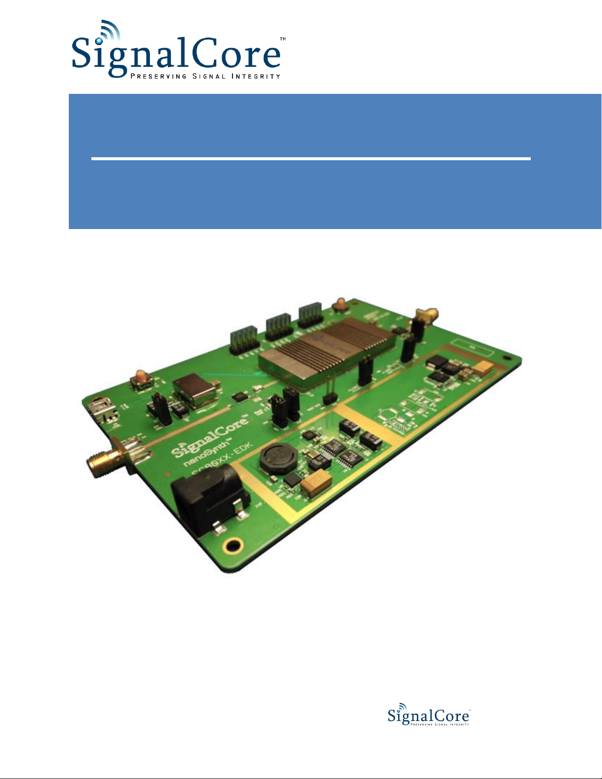
Evaluation Development Kit Description
Figure 1. SC800 evaluation development kit.
Label
Description
A
SC800 nanoSynth.
B
Reference input SMA connector. Typical input power is 7 dBm. Max input power is
10 dBm. Input frequency is either 100 MHz or 200 MHz.
C
RF output SMA connector.
D
+12V supply connector, 2.5 mm jack.
E
Mini-B type USB connector for USB communication to the SC800 device .
F
SPI communication header pins. The SRDY pin can be used to monitor the status of
the SPI interface. Refer to the SPI interface section in the product datasheet to learn
how to properly communicate with the device through this interface.
Errata: The label on the PCB has SDO and SDI swapped.

Rev 1.1 | Page 5 of 20
SC800 EDK User Guide
G
External control header pins: SMODE, LCK STATUS, TRIG2 (TRIG IN), and TRIG1
(TRIG OUT). Use the supplied jumpers to shunt each pin to ground as required. See
the product datasheet for more information about each signal pin.
H
These are dual function pins. The JTAG functionality can be ignored for normal
operation. See the product datasheet for information about each signal pin.
I
100 MHz VCXO. This VCXO is enable by shunting jumper header J7. If the shunt is
removed, the VCXO is turned off, and the path to the SC800 reference input is
switched to the on-board SMA connection (B).
J
+5.5V supply switcher. Regulated to +5V, +4V, and +3.3V. The SC800 only runs off
the +4V supply. The other rails are used to power the VCXO and the digital circuitry.
K
-5.5V supply switcher. Regulated to -5V. Used only by the output driver amplifier
(L).
L
RF buffer amplifier. This amplifier boosts the output power to +20 dBm (typical).
M
Reset button. Press the reset button to ensure the device properly operates.
N
USB in-system programming button.
Verifying the Contents of Your Shipment
The contents of the product package should include the following items:
1. One SC800 EDK board
2. One 12V power supply wall adapter
3. One USB cable
4. One SC800 EDK Getting Started Guide document
Inspect the shipping carton for visible damage. If the carton is damaged please notify the carrier and
SignalCore immediately.
The SC800 EDK ships in antistatic packaging to prevent damage from electrostatic discharge (ESD).
The device should always be stored inside an antistatic bag when it is not in use as ESD can cause
damage to the electronic components on the board. Properly ground yourself and use ESD good
practices when handling the product at all times.
Open the shipping carton and remove all contents. If the contents show visible damage and/or are
missing, please contact SignalCore immediately.
ESD
CAUTION

Rev 1.1 | Page 6 of 20
SC800 EDK User Guide
Control Software and Device Driver
The SC800 EDK comes with a USB flash drive that contains everything needed to install, control,
and program the SC800. Insert the USB drive into the host computer and launch "SC800 EDK
Installer.exe". This top-level menu-based window allows for independent installations of the SC800
software set and the National Instruments LabVIEW Run-Time Engine needed to operate the
SC800 Soft Front Panel application. The run-time engine installation can be skipped if LabVIEW
2010 or later is already installed on the host computer. The SC800 software installation files are also
available online at www.signalcore.com. Navigate to the SC800 product page; a link to the control
and device driver software can be found under the "Library" tab. There are two executables listed -
SC800 Setup32.exe and SC800 Setup64.exe. Choose the right one for your operating system, then
download and launch the setup file. Whether you use the USB drive for setup or download the files
online, running the setup executable will only install the control and development software to your
computer and does not install the device driver. The driver must be installed manually by following
the instructions in the next section.
Installing the USB Driver
The following driver installations steps apply to Windows 7TM. These steps are also sufficient to
guide the device driver installation for Window XPTM.
1. Power on the device and connect it the host PC. Window 7 will attempt to install the
driver, but will fail because the driver has not been loaded. Click the arrow pointer
at the lower right corner of the screen and the following screen should appear:

Rev 1.1 | Page 7 of 20
SC800 EDK User Guide
2. Click on the button, and in the search input box type “mmc devmgmt.msc” as
shown below, then press [ENTER].
3. This will bring up the "Device Manager" screen as shown below. Right click on “SC800X
nanoSynth” and select “Update Driver Software”.

Rev 1.1 | Page 8 of 20
SC800 EDK User Guide
4. The "Update Driver Software" screen will appear. Select "Browse my computer for driver
software."
5. Select "Let me pick from a list of device drivers on my computer", then click [Next] to
continue.

Rev 1.1 | Page 9 of 20
SC800 EDK User Guide
6. Select “Show All Devices” and click [Next] to continue.
7. On the following 2 screens, click [Have Disk…]

Rev 1.1 | Page 10 of 20
SC800 EDK User Guide
8. On the next screen browse to or type in the directory location where the sc800.inf file
resides. If you used the default install location for the Setup32 or Setup64 executable,
the INF file will be located under C:\Program Files\SignalCore\SC800. Select the
appropriate directory and click [OK].
Table of contents
Other SIGNALCORE Microcontroller manuals

Popular Microcontroller manuals by other brands

AMS
AMS AS7261 Demo Kit user guide

Novatek
Novatek NT6861 manual

Espressif Systems
Espressif Systems ESP8266 SDK AT Instruction Set

Nuvoton
Nuvoton ISD61S00 ChipCorder Design guide

STMicrolectronics
STMicrolectronics ST7 Assembler Linker user manual

Texas Instruments
Texas Instruments Chipcon CC2420DK user manual


Texas Instruments
Texas Instruments TMS320F2837 D Series Workshop Guide and Lab Manual

CYPRES
CYPRES CY14NVSRAMKIT-001 user guide

Texas Instruments
Texas Instruments INA-DUAL-2AMP-EVM user guide

Espressif Systems
Espressif Systems ESP8266EX Programming guide

Abov
Abov AC33M8128L user manual

Laird
Laird BL654PA user guide