
Sideshift PT230 PONTOON THRUSTER User manual

PT230 PONTOON
THRUSTER
(PATENT PENDING)
INSTALLATION MANUAL
VOLUME 1.2, JUNE 2015
Sideshift Inc. 130 Industrial Ave, Unit 303, Carleton Place, ON, Canada K7C 3T2
1.877.325.4787 +613.686.6011 INFO@SIDESHIFT.COM

SIDESHIFT INSTALLATION GUIDE V1.0
1
INTRODUCTION
Thank you for your purchase of a Sideshift thruster system.
Sideshift thrusters are designed for easy installation by anyone with basic mechanical
and electrical skills.
This manual explains everything you need to know about installing your Sideshift
thruster.
We also provide unlimited telephone support at
1.877.325.4787.
Also see our website for helpful installation videos at
sideshift.com/choose-sideshift/videos/videos/.
This manual explains the mounting and operation of the PT230 Pontoon Thruster
system. For electrical and joystick connections and installation, tools and
procedures, as well as maintenance and troubleshooting, please refer to our master
installation manual for 230/340/350 series thrusters.
We recommend that you familiarize yourself with both manuals before starting your
installation.

SIDESHIFT INSTALLATION GUIDE V1.0
2
Safety warnings
WARNING: To prevent overheating when operating the Sideshift
thruster, run in short bursts for a maximum of 20 seconds
at a time, then allow to cool for at least 10 seconds before
further operation.
WARNING: Ensure main ignition is turned off and motor control breakers are
open when conducting maintenance and repair of the thruster.
WARNING: Use extreme caution when swimmers are in the area of the thruster.
Turn off ignition and avoid contact with thruster props when boat is
stationary.
WARNING: When operating out-of-water do not run thruster for longer than
5 seconds to prevent overheating.
WARNING: If conducting an in-water installation, use a cordless drill only, as a
corded drill can present an electrocution hazard.
Required Tools
Heat gun
3/8” drive cordless driver
3/8” hex socket
Wire stripper
Wire crimper
SAE wrench set 3/8” to 3/4”
Pliers
Drill bits up to ½”
Caulking gun
1 ¼” and 2 ½” hole saw
Dremel-type rotary cutting tool
SIDESHIFT INSTALLATION GUIDE V1.0
3
INSTALLATION INSTRUCTIONS
–PT230 PONTOON THRUSTER
Sideshift thrusters can be installed with the boat in water or on land, although land-
based installation is easier.
Get an overview of the installation procedures by viewing the installation videos on-
line at sideshift.com/choose-sideshift/videos/videos/.
PT230 Thruster Placement
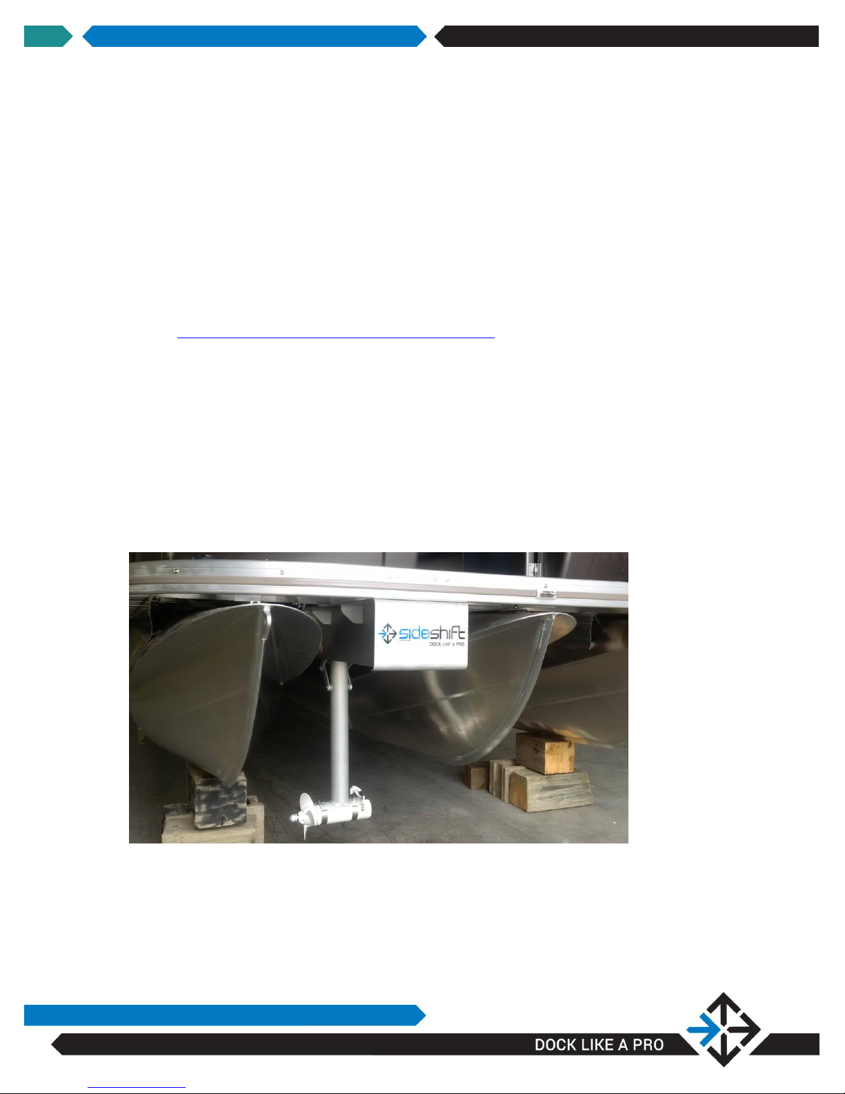
The thruster is designed to be positioned on the underside bow of any dual or tri-
pontoon boat. For tri-pontoon boats position the thruster between two pontoons on
the helm side of the boat which will facilitate wire-runs. For dual pontoons position
the unit centrally between pontoons.
The cables and air vent line pass through the deck and into storage typically found
under a hinged bench above deck.

SIDESHIFT INSTALLATION GUIDE V1.0
4
Step-By-Step Instructions:
STEP 1: DETERMINE THE DISTANCE BETWEEN MOUNTING CROSS
MEMBERS
The unit has pre-drilled mounting slots to accommodate either 16” or 24”
centers. In some installations it will be necessary to drill the thruster
mounting plate as seen below, to fit centers other than 16” or 24” using a
¼” drill bit.

SIDESHIFT INSTALLATION GUIDE V1.0
5
NOTE: You will require a helper for Step 2
NOTE: The thruster can be positioned at the bow or further back on the
boat where it is less visible
STEP 2: POSITION THRUSTER AND ATTACH TO UNDERSIDE OF
DECK
a. Using a helper, position the thruster in place, and using the supplied
self—drilling/self-tapping 1 ¼” stainless hex-head mounting screws, apply
a small amount of supplied Loctite to the threads and drive the screws
into the aluminum cross-members at the appropriate location. Pilot holes
are not required. Two screws are required at the front and two at the
back of the unit.

SIDESHIFT INSTALLATION GUIDE V1.0
6
STEP 3: FEED WIRES AND AIR LINE THROUGH DECK
a. Determine a location for the motor control box, ideally in a dry storage
area close to the bow on the helm side of the boat.
b. Using a 1 ¼” hole saw, drill holes at appropriate locations for routing of
the thruster cables, actuator cable and air vent line.
Feed the thruster cables, blue actuator cable and air line into the storage
location.
c. Drill a 1 ¼” hole (if required) to access the helm area. Route the
actuator cable under the helm for connection to the control module.
Route the motor control cables under the helm for connection to a
dedicated 12v battery
or
to your main 12v house battery.
d. Route a charge line from your house battery to the thruster battery (if
required).
WARNING: Verify that hole placement will not interfere with or damage
anything when drilling through the deck and storage location, and
that there is sufficient space so that cables can be accessed after
passing through the proposed hole location.
WARNING: Ensure the control box is located in a dry storage area

SIDESHIFT INSTALLATION GUIDE V1.0
7
NOTE: The air line prevents pressure buildup on the seals due to
temperature changes. The air line must not be crimped, and must
be positioned so that the open end is in a dry location
STEP 4: CONTROL BOX AND BATTERY CONNECTIONS
Refer to page 39 of the master installation manual.
STEP 5: CONNECTING JOYSTICK AND ACTUATOR CONTROLS
a. Plug the green connector from the control module into the joystick base.
Note the connector is keyed to fit only one way. Align the label as seen in
the image.
b. Position the white control module in a dry location under the helm.
c. Find an appropriate location on your dash for the actuator control switch.
Using the template provided, create a mounting hole using a dremel-type
rotary cutting tool.
d. Plug the white switch cable into the control module.
e. Connect the “battery neg” leads to the motor control box.
f. Connect “Switch 1” and “Switch 2” leads to the motor control box.

SIDESHIFT INSTALLATION GUIDE V1.0
8
g. Route the blue actuator cable from the motor control box to the white
control module under the helm.
h. Plug the blue actuator cable into the control module.
i. Connect the red and black wires from the control module to power and
ground in the helm. You may choose to connect power through an
accessory switch on your helm.

SIDESHIFT INSTALLATION GUIDE V1.0
9
STEP 6: INSTALL JOYSTICK ON CONSOLE
a. Locate a position on the console of the boat suitable for the joystick.
Check under the selected position on the console to ensure a minimum
area of at least 4” diameter and a minimum three inches obstruction-free
below the area of the joystick equipment.
b. Tape in place the template supplied with the joystick (see above)
c. (Optional) Drill the three holes marked on the template using a 3/16” bit.
d. Using the same bit as for Step C above, drill a hole at the center of the
template, marked by the cross-hairs.
e. Using a 2.5” hole saw and the pilot hole drilled in Step D above, drill a
hole at the center of the template.
Other manuals for PT230 PONTOON THRUSTER
1
Table of contents
Other Sideshift Boat manuals

Popular Boat manuals by other brands


PURSUIT
PURSUIT OS 335 owner's manual

Boston Whaler
Boston Whaler CONQUEST 345 owner's manual

Jeanneau
Jeanneau SUN ODYSSEY 41 DS owner's manual

Meridian
Meridian 490 Pilothouse owner's manual

Advanced Elements
Advanced Elements AdvancedFrame Expedition AE1009 owner's manual

Robo Marine Indonesia
Robo Marine Indonesia GEOMAR user manual


