Showerbuddy SB2 User manual

elimination through innovation
SB2
TubBuddy
Owners Manual
page0_SB2_owners_manual_front_cover.indd 1 25/11/2009 4:06:36 p.m.

page1_SB2_owners_manual_blank1.indd 2 25/11/2009 4:07:12 p.m.

contents
page 2
Exploded Parts ............................................................... 3
Parts List ........................................................................ 4
Securing Clip Sizes ......................................................... 4
TubBuddy Assembly ....................................................... 5
TubBuddy Setup ............................................................. 12
TubBuddy Operation ....................................................... 17
Cleaning + Maintenance ................................................. 21
Safety Instructions ......................................................... 22
Warranty Information ...................................................... 25
Registration Form ........................................................... 28
SB2 TubBuddy
page2_SB2_owners_manual_contents.indd 2 25/11/2009 4:08:59 p.m.

exploded parts
page 3
9
15
17
22
23
11
2
3
4
10
8
13
12
14
6
5
7
16
18
19
20
21
SB2 TubBuddy
7
6
25
27
24
4
26
29
28
1
page3_SB2_owners_manual_exploded_parts.indd 2 25/11/2009 4:11:14 p.m.

parts list
page 4
15” Castor Wheel
2Height Adjustment Tubes (Wheeled Base)
Base Legs
3
Securing Clip (Large)4
Wheeled Base Track5
Adjustment Knob (Large)6
Tube Washer
7
Seat Base8
Track Wheels9
Secondary Brake10
11 Primary Brake
12 Back Rest
Arm Rest (Right)
13
Arm Rest (Left)14
15 Arm Rest Knob
16 Arm Rest Clip
Arm Rest Lock
17
Cushion18
Cushion Connectors19
Commode Bucket20
Height Adjustment Tubes (Bath Base)
21
Bath Base Leg (Front)22
Bath Base Leg (Back)23
See the exploded chair image for the location of parts.
securing clip sizes
Use the images below as a reference to check the provided securing clips to ensure that
the correct size is used where required.
Small Medium Large
SB2 TubBuddy
Bath Base Track
24
Bridge25
Foot Rest (Wheeled Base)26
Foot Rest (Bath Base)27
Stabilising Tubes
28
Rubber Feet29
page4_SB2_owners_manual_parts+clips.indd 2 25/11/2009 4:12:19 p.m.

step 2
SB2 TubBuddy
page 5
Insert both height adjustment tubes into
the base legs. Ensure the holes on the
height adjustment tubes align with the
holes on the base legs.
Secure both height adjustment tubes at
the required height using 1 large securing
clip on each base leg.
NOTE
- Each height adjustment hole raises the
seat base 1”.
- Check to ensure all securing clips are
fully inserted.
- Ensure both height adjustment tubes are
aligned at the same height.
step 1 assembly
Using the grooves on the underside of
the wheeled base track as a guide, place
the wheeled base track onto the height
adjustment tubes.
Position the wheeled base track on the
height adjustment tubes so that the 4
threaded holes on the wheeled base track
are aligned with the 4 holes on the top of
the height adjustment tubes.
Secure the wheeled base track in
position by screwing 1 large fixing knob
and tube washer through each of the 4
holes in the height adjustment tubes and
into the threaded holes on the wheeled
base track.
page5_SB2_owners_manual_assembly1+2.indd 2 25/11/2009 3:18:31 p.m.

step 4
SB2 TubBuddy
page 6
step 3
Insert the back rest into the seat base.
Slide the back rest into the seat base until
the clip pins click into the holes on the
seat base.
The clip pins secure the chair back frame
in position.
NOTE
- To remove the seat back press the clip
pins in and slide the seat back out of the
seat base.
With the wheeled base track assembled
on a flat surface apply the brakes on the 4
castor wheels.
Slide the seat base into the wheeled
track by aligning the track wheels with
the grooves in the track. When inserting
the seat base into the track there will
be 4 clicks as the track wheels pass the
secondary brakes.
Slide the seat base into the track until the
primary brakes secure the seat base in
position.
page6_SB2_owners_manual_assembly3+4.indd 2 25/11/2009 3:21:54 p.m.

step 6
SB2 TubBuddy
page 7
step 5
Insert the arm rests into the sockets on
the seat base until the clip pin clicks and
locates the arm rests in position.
Screw the arm rest knob into the arm rest
to firmly secure the arm rest in position.
Swing the arm rest forward so that it locks
into position in the arm rest clip.
Slide the arm rest lock over the arm rest
clip to lock the arm rest in position.
By sliding the armrest lock you can easily
swing the armrest out of the way or
secure the armrest in position.
To unlock the armrest slide the armrest
lock away from the armrest.
To lock the armrest slide the armrest lock
towards the armrest.
NOTE
- The armrest locks should always be used
when the armrests aren’t in the swing
away position.
page7_SB2_owners_manual_assembly5+6.indd 2 25/11/2009 3:22:48 p.m.

step 8
SB2 TubBuddy
page 8
step 7
The armrests can be easily swung-away
when required.
Unlock the armrest by sliding the armrest
lock away from the armrest. Once this is
done the armrest can be swung away. The
clip pin which secures the armrest in
position stops the armrest from rotating
to far.
NOTE - The armrest locks should always
be used when the armrests aren’t in the
swing-away position.
Ensuring the correct orientation attach
the seat cushion to the seat base by
pushing the 4 locating lugs on the
underside of the cushion into the
connectors on the seat base.
Firmly press the cushion into position
so that the 4 locating lugs are securely
located in the connectors.
NOTE
- To remove the cushion, carefully remove
one lug at a time from the connectors until
all 4 locating lugs are removed.
page8_SB2_owners_manual_assembly7+8.indd 2 25/11/2009 3:23:51 p.m.
step 10
SB2 TubBuddy
page 9
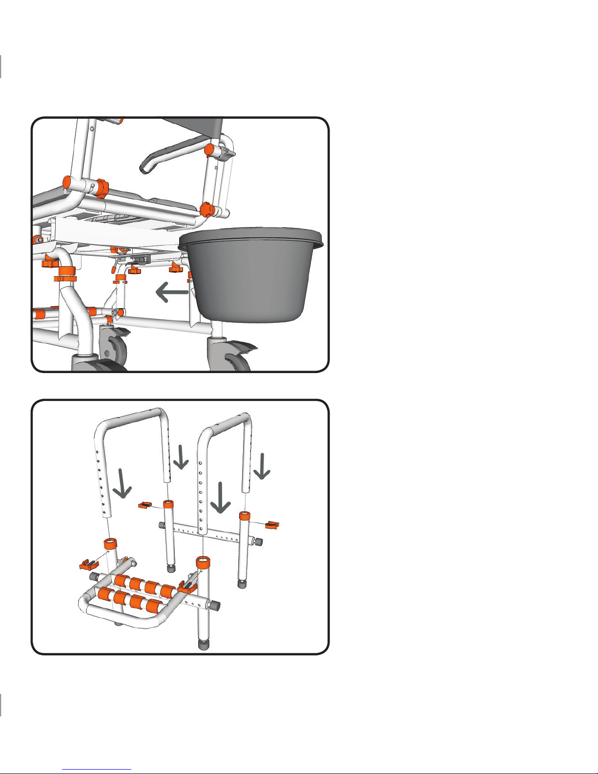
step 9
Rotate the chair so that you have easy
access to the underside of the seat base.
From the back of the chair slide the
commode bucket into the 2 brackets on
the underside of the seat base.
Ensure the commode bucket is pushed in
far enough that the brackets securely hold
the commode bucket in position. The
commode bucket should be centred under
the opening in the cushion.
Insert both height adjustment tubes into
the bath base legs. Ensure the holes on
the height adjustment tubes align with the
holes on the bath base legs.
Secure both height adjustment tubes at
the required height using 1 large securing
clip on each base leg.
NOTE
- Each height adjustment hole raises the
seat base 1”.
- Check to ensure all securing clips are
fully inserted.
- Ensure both height adjustment tubes are
aligned at the same height.
page9_SB2_owners_manual_assembly9+10.indd 2 25/11/2009 3:25:02 p.m.
Table of contents
Other Showerbuddy Wheelchair manuals