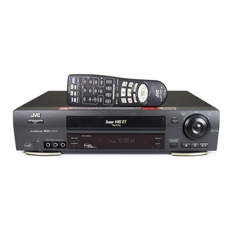
Sharp VC-A592U User manual

1
VC-A592U
VC-H992U
SHARP CORPORATION
VIDEO CASSETTE RECORDER
MODELS
In the interests of user-safety (Required by safety regulations in some
countries) the set should be restored to its original condition and only parts
identical to those specified be used.
VC-A592U
VC-H992U
SERVICEMANUAL
CONTENTS
Page
1. GENERAL INFORMATION .............................. 4
1-1 FEATURES .................................................4
1-2 SPECIFICATIONS ..................................... 4
1-3 LOCATION OF MAJOR COMPONENTS
AND CONTROL ......................................... 5
2. DISASSEMBLY AND REASSEMBLY .............. 6
2-1 DISASSEMBLY OF MAJOR BLOCKS....... 6
2-2 DISASSEMBLING THE MECHANISM/
MAIN PWB ASSEMBLY............................. 7
2-3 CARES WHEN REASSEMBLING.............. 8
3. FUNCTION OF MAJOR MECHANICAL
PARTS ..............................................................9
4. ADJUSTMENT, REPLACEMENT AND
ASSEMBLY OF MECHANICAL UNITS.......... 11
4-1 MECHANISM CONFIRMATION
ADJUSTMENT JIG .................................. 11
5. ELECTRICAL ADJUSTMENT ........................ 30
5-1 ADJUSTMENT OF HEAD SWITCHING
POINT .......................................................31
Page
5-2 ADJUSTMENT OF FV (False Vertical Sync)
OF STILL PICTURE................................. 31
5-3 CHECKING OF OFF TRACK ................... 31
5-4 ADJUSTMENT OF SIF-INPUT LEVEL .... 32
5-5 ADJUSTMENT OF STEREO
SEPARATION ...........................................32
6. MECHANISM OPERATION FLOWCHART
AND TROUBLESHOOTING GUIDE .............. 33
7. TROUBLESHOOTING ................................... 39
8. BLOCK DIAGRAM ..........................................50
9. SCHEMATIC DIAGRAM AND PWB FOIL
PATTERN .......................................................58
10.PARTS LIST....................................................72
11.EXPLODED VIEW OF MECHANICAL
PARTS ............................................................79
12.PACKING OF THE SET ................................. 83
S39E8VCA592UL

2
VC-A552U
VC-H992U
IMPORTANT SERVICE NOTES
WARNING :TOREDUCETHERISKOFFIREORELEC-
TRIC SHOCK, DO NOT EXPOSE THIS AP-
PLIANCE TO RAIN OR MOISTURE.
RISK OF ELECTRIC SHOCK
DO NOT OPEN
CAUTION
CAUTION: TO REDUCE THE RISK OF ELECTRIC SHOCK. DO
NOT REMOVE COVER. NO USER-SERVICEABLE
PARTS INSIDE. REFER SERVICING TO QUALIFIED
SERVICE PERSONNEL.
This symbol warns the user of uninsulated voltage
withintheunitthatcancausedangerouselectricshocks.
This symbol alerts the user that there are important
operatingandmaintenanceinstructionsintheliterature
accompanying this unit.
This symbol mark means fast operating fuse.
For continued protection against risk of fire, replace
only with same type fuse F901 (3.0A, 125V).
CAUTION:
BEFORE RETURNING THE VIDEO CASSETTE
RECORDER
Beforereturning the videocassette recorder tothe user,
perform the following safety checks.
1. Inspect all lead dress to make certain that leads are
not pinched or that hardware is not lodged between
thechassisandothermetalpartsinthevideocassette
recorder.
2. Inspect all protective devices such as non-metallic
control knobs, insulation materials, cabinet backs,
adjustmentandcompartmentcoversorshields,isola-
tion resistor/capacitor networks, mechanical insula-
tors etc.
3. To be sure that no shock hazard exists, check for
current in the following manner.
●Plug the AC line cord directly into a 120 volt AC outlet
(Do not use an isolation transformer for this test).
●Using two clip leads, connect a 1.5k ohm, 10 watt
resistorparalleledbya0.15µFcapacitorinserieswith
all exposed metal cabinet parts and a known earth
ground, such as a water pipe or conduit.
●Use an SSVM or VOM with 1000 ohm per volt, or
higher, sensitivity or measure the AC voltage drop
across the resistor (See Diagram).
●Move the resistor connection to earth exposed metal
part having a return path to the chassis (antenna,
metalcabinet,screwheads,knobsandcontrolshafts,
SSVM
AC SCALE
1.5k ohms.
10W
CONNECT TO
KNOWN EARTH
GROUND
TO EXPOSED
METAL PARTS
0.15 µF
TEST PROBE
etc.) and measure the AC voltage drop across the
resistor. Reverse the AC plug on the set and repeat
AC voltage measurements for each exposed part.
Anyreading of0.45V rms (thiscorresponds to0.3mA
rms AC.) or more is excessive and indicates a poten-
tial shock hazard which must be corrected before
returning the video cassette recorder to the owner.
3.0A 125V

3
VC-A592U
VC-H992U
PRECAUTIONS IN PART REPLACEMENT
When servicing the unit with power on, be careful to the section marked white all over.
This is the primary power circuit which is live.
When checking the soldering side in the tape travel mode, make sure first that the tape has been loaded and then turn
over the PWB with due care to the primary power circuit.
Make readjustment, if needed after replacement of part, with the mechanism and its PWB in position in the main frame.
(1) Start and end sensors: Q701 and Q702
Insert the sensor’s projection deep into the upper hole of the holder. Referring to the PWB, fix the sensors tight
enough.
(2) Photocoupler: IC901
Refer to the symbol on the PWB and the anode marking of the part.
(3) Cam switches A and B: D708 and D709.
Adjust the notch of the part to the white marker of the symbol on the PWB. Do not allow any looseness.
(4) Take-up and supply sensors: D707 and D706.
Be careful not to confuse the setting direction of the parts in reference to the symbols on the PWB. Do not allow any
looseness.

4
VC-A552U
VC-H992U
1. GENERAL INFORMATION
1-1 FEATURES
• 400 Times Rewind Speed to Fast Forward and Rewind
• EZ Set Up
• S-VHS Quasi Playback
• Double Azimuth 4-Head
•19
µm Clear Picture System (in EP Mode)
• HQ System for Better Resolusion and color Reproduc-
tion
• Multi-Language (English/Spanish/French) OSD (On
Screen Display) with Menu Screen Guidance
• 181-ch PLL Quartz Synthesized Random Access Tuner
with Automatic Channel Setting
• Quick Start with Full Loading Mechanism
• 1-Year, 8-Event Programmable Timer
• Simple Recording Timer
• Univarsal Remote Control
• SHARP Super Picture
• 20 seconds Timer Backup
• Field-Still/Variable Slow/Frame Advance
• Real-Time Counter
• Automatic Daylight Saving-Time (D.S.T.)Adjustment
• Blue Screen Noise Elimination
• Automatic Tracking Control System
• Digital Program Search System (DPSS)
• Skip Search
• Instant Replay
• Auto Zero Back
• Recorded Section Auto Repeat
• Full Automatic Playback
• Function Lock
• Up to 8 Hours of Recording/Playback (with T-160 cassette)
• Automatic Head Cleaning System
• Built-in MTS (Multi-channel TV Sound) Detector
(VC-H992U)
1) Recording system Format: VHS NTSC Standard
Luminance signal: FM recording
Chroma signal: Low frequency converted direct recording
Color system: NTSC
Number of video head: 4
Tape speed: (SP) 33.35 mm/sec
(LP) 16.67 mm/sec (Playback only)
(EP) 11.12 mm/sec
2) Video signal Input level: 0.5 ~ 2.0 Vp-p, 75 ohm unbalanced
Output level: 1.0 Vp-p, 75 ohm unbalanced
Horizontal resolusion: 220 lines (SP mode)
Signal to noise ratio: 45dB (SP mode)
3) Audio signal Input level: – 8 dBs (309mVrms, 47k ohm)
Output level: – 8 dBs (309mVrms, 1k ohm)
Frequency response: 80Hz ~ 10kHz (SP mode linear)
Signal to noise ratio: 43dB (SP mode linear)
Hi-Fi dynamic range: 90dB
HI-Fi Frequency response: 20Hz ~ 20kHz
Hi-Fi Wow and flutter: 0.005% max. with T-120 tape
4) Receiving channel VHF: Channels 2 ~ 13
UHF: Channels 14 ~ 69
CATV: Channels A-8, A-5 ~ W + 84
Antenna Input Impedance: 75 ohm
5) Misc. Fast forward /Rewind time: Approximate 54 second with T-120 cassette
Power source: 120V AC, 60 Hz
Power consumption: 20 W
Allowable ambient temperature: with T-120 tape 5°C to 40°C (41°F to 104°F)
Operating humidity: below 80% RH
Dimensions: 360 (W), 92 (H), 253 (D) mm (14-3/16, 3-5/8, 9-31/32 inch)
Weight: 2.8 kg (6.2 lbs)
Accessories included: 75 ohm coaxial cable, Operation manual, Timer setting card,
Infrared remote control, Dry Battery (2 pcs.)
Note: Specifications may be changed for improvement without notice.
1-2 SPECIFICATIONS

5
VC-A592U
VC-H992U
1-3 LOCATION OF MAJOR COMPONENTS AND CONTROL

6
VC-A552U
VC-H992U
SHARP
4
2
B
C
A
B
5
9
6
10
11
7
8
3
3
C
1
A
12
2. DISASSEMBLY AND REASSEMBLY
2-1 DISASSEMBLY OF MAJOR BLOCKS
TOP CABINET : Remove 2 screws 1.
FRONT PANEL : Remove button 2.
Remove 2 screws 3and 7 clips 4.
OPERATION : Remove 1 screw 5.
PWB
SHIELD ANGLE : Remove1screws6withshieldangle.
MECHANISM/ : Remove 1 screw 7, 1 screw 8, 2
MAIN PWB screws 9, 2 screws 0. Remove 1
screwqwithantennaterminalcover.
Remove 1 screw wwith top cabinet
fix angle.
FRONT PANEL
TOP CABINET
SHIELD
ANGLE
ANTENNA
TERMINAL
COVER
MECHANISM/
MAIN PWB
ASSEMBLY
TOP CABINET
FIX ANGLE
MAIN FRAME
OPERATION
PWB
H/A SHIELD
TOP

7
VC-A592U
VC-H992U
2-2 DISASSEMBLING THE MECHANISM/MAIN PWB ASSEMBLY
1. When removing the mechanism from the main PWB,
removetheantennacover1screw1,andremovethe
antenna cover.
Remove the PWB bottom plate 1 screw 2.
Remove the FFC cable (AA, AD, AH) 3which con-
necting the PWB and the mechanism.
Take out vertically the mechanism so that it does not
damage the adjacent parts.
2. Removing the mechanism and cassette housing.
Remove2screws4fixingthecassettehousingtothe
mechanism, and remove the cassette housing.
MECHANISM CHASSIS
2
1
3
4
CASSETTE
HOUSING
MAIN PWB

8
VC-A552U
VC-H992U
START SENSOR
cassette housing. (Conditions: When mechanism and
PWB have been installed)
2. Mechanical initial setting
Feed the pulley feed gear of loading motor with screw
driver. After ascertaining the return to the initial set posi-
tion (*1) install the cassette housing in the specified
position.(Thismethodisappliedonlyforthemechanism.)
PARTS WHICH NEED PARTICULAR CARE
Wheninstalling themechanism chassison thePWBunit,
take care so as to prevent deformation due to contact of
mechanism chassis with REC TIP SW.
Pulley feed gear
Screwdriver
AE CONNECTOR
AL CONNECTOR
Casecon
drive gear
Drive angle of
cassette housing
REC TIP SW
END SENSOR
AC CONNECTOR
Tilt mark (*1)
INSTALLING THE CASSETTE HOUSING
Whenthecassettehousingisinstalledonthemechanism,
the initial setting is essential condition.
There are two initial setting methods, namely electrical
and mechanical.
1. Electrical initial setting
So as to perform initial setting of mechanism execute the
Step1 ofInstallation of cassettehousing. Afterascertain-
ing the return to the initial setting position (*1) install the
2-3 CARES WHEN REASSEMBLING
INSTALLING THE MECHANISM ON PWB
Lower vertically the mechanism, paying attention to the
mechanism edge, and install the mechanism with due
care so that the parts are not damaged. So as to fix the
mechanismtothemainPWBinstalltwohousings.(Fit the
antenna cover to one of them. For other, fix the vicinity of
loading motor and solder joint side of main PWB.) Con-
nect again the FFC cable (AA-MH, AD-ME, AH-MH)
between the mechanism and the main PWB.

9
VC-A592U
VC-H992U
3. FUNCTION OF MAJOR MECHANICAL PARTS (TOP VIEW)
No. Function No. Function
1 Full erase head
2 Sup pole base ass’y
3 Tension arm
4 Idler ass’y
5 Pinch drive lever ass’y
6 Supply reel disk
7 Sup main brake
8 Tu main brake
9 Pinch drive cam
10 A/C head ass’y
11 Reverse guide
12 Casecon drive gear
13 Take-up reel disk
14 Pinch roller lever ass’y
1715 10
11
5
9
14
12
8
16
13
4
6
2
7
3
1
18

10
VC-A552U
VC-H992U
FUNCTION OF MAJOR MECHANICAL PARTS (BOTTOM VIEW)
No. Function No. Function
15 Drum ass’y
16 Loading motor
17 Drum drive motor
18 Tu pole base ass’y
19 Slow brake
20 Master cam
21 Capstan D.D. motor
22 Reel belt
23 Clutch lever
24 Limiter pulley ass'y
26 Shifter
26
24
21
22
19
20
12
23
Other manuals for VC-A592U
1
This manual suits for next models
1
Table of contents
Other Sharp VCR System manuals

Sharp
Sharp VC-MH703HM User manual

Sharp
Sharp VC-A410X User manual

Sharp
Sharp VC-A410U User manual

Sharp
Sharp VC-MH714HM User manual

Sharp
Sharp VC-A560UA User manual

Sharp
Sharp VC-MH75HM User manual

Sharp
Sharp VC-D810S User manual

Sharp
Sharp VC-A136X User manual

Sharp
Sharp VC-A565U User manual

Sharp
Sharp VC-S2000GM User manual

Sharp
Sharp VC-H998U User manual

Sharp
Sharp VC-MH741SM User manual

Sharp
Sharp VC-S2000HM Quick start guide

Sharp
Sharp VC-G20SM User manual

Sharp
Sharp VC-780E User manual

Sharp
Sharp VC-TA350 User manual

Sharp
Sharp VC-H800X User manual

Sharp
Sharp VC-MH711GM User manual

Sharp
Sharp VC-A412U User manual

Sharp
Sharp VC-488NS User manual