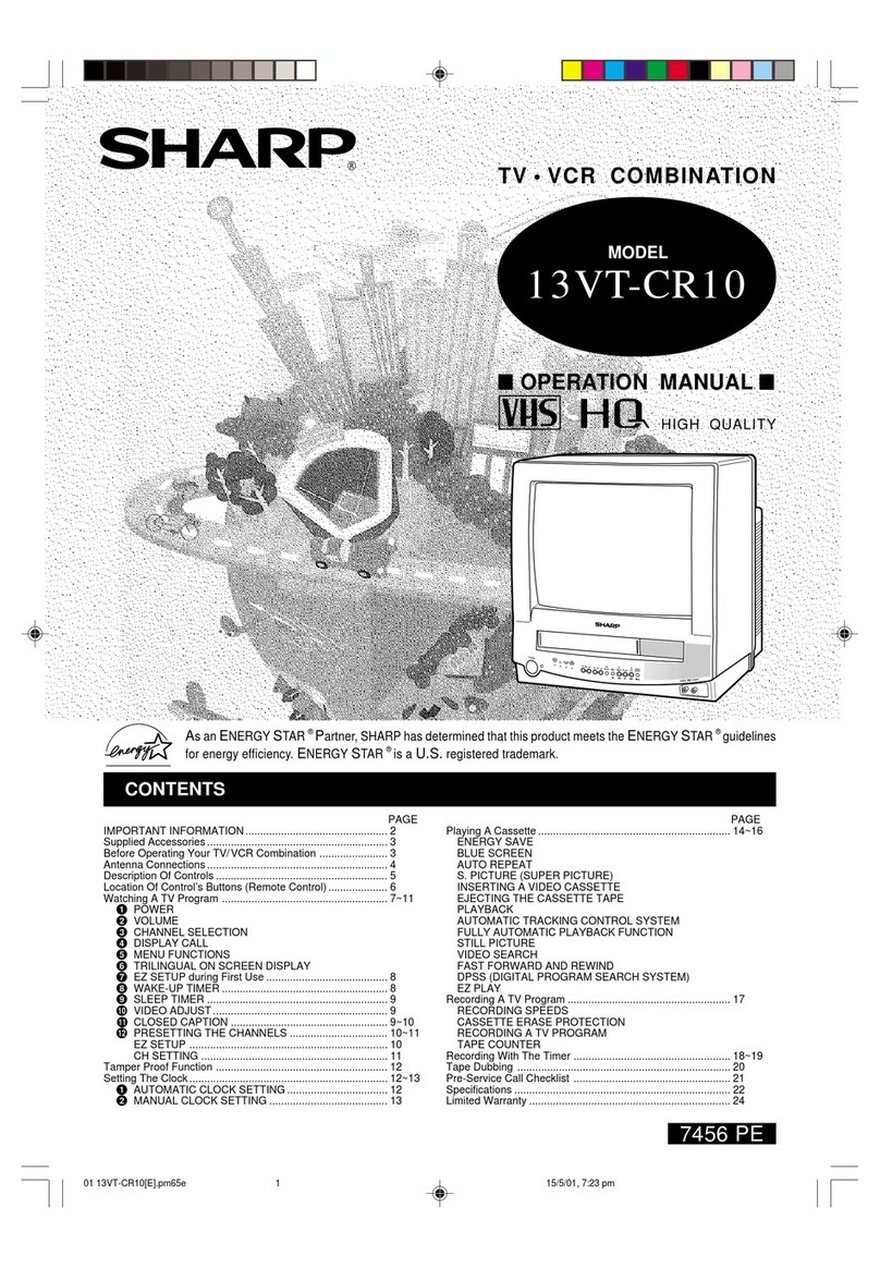
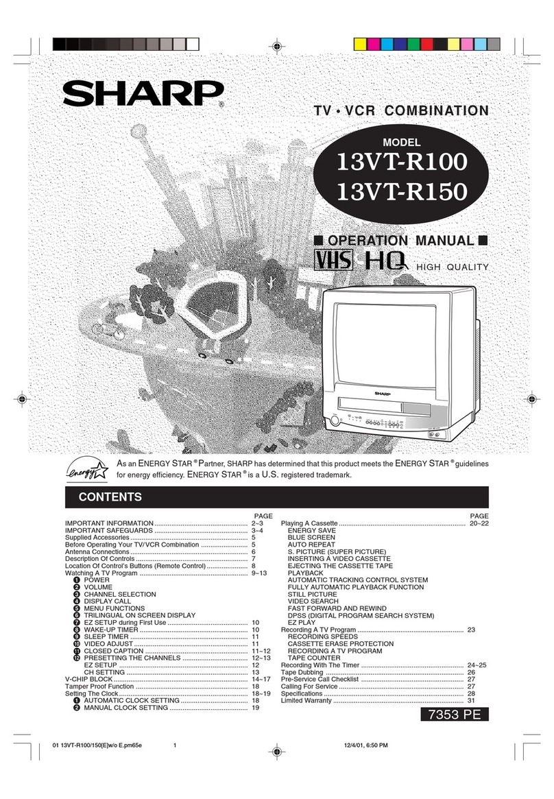
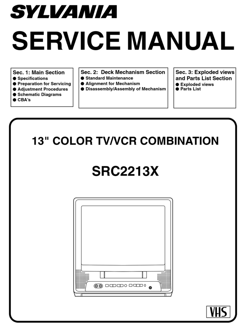
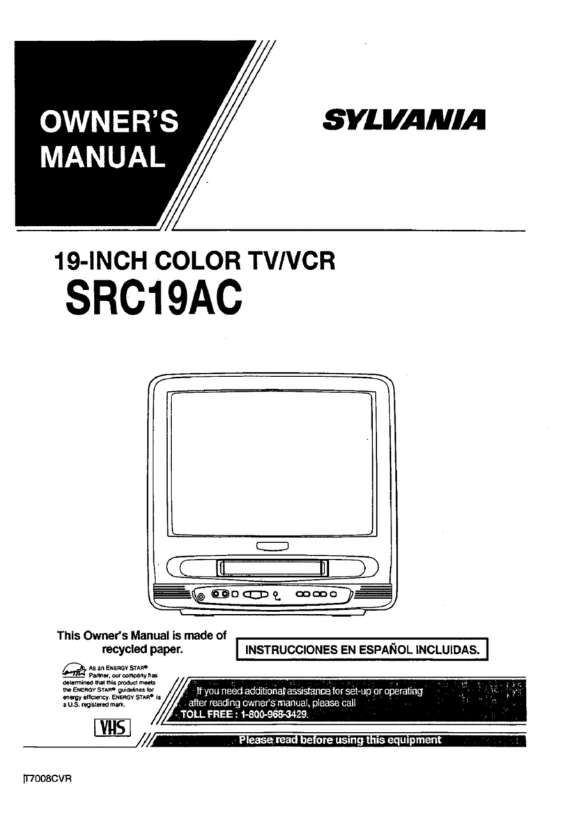
Sharp 25VT-K100 User manual

25VT-K100
25VT-CK10
1
CONTENTS
In the interests of user-safety (Required by safety regulations in some countries ) the set should be restored to its
original condition and only parts identical to those specified should be used.
Page
æIMPORTANT SERVICE SAFETY PRECAUTION .....................................................................................2
æELECTRICALSPECIFICATIONS .............................................................................................................6
æLOCATION OF USER’S CONTROL .........................................................................................................7
æDISASSEMBLYAND REASSEMBLY .......................................................................................................9
æINSTALLATION AND SERVICE INSTRUCTIONS..................................................................................12
æPRECAUTIONS IN REASSEMBLING
(Refer to 13VT-J100 Service Manual)
æFUNCTION OF MAJOR MECHANICALPARTS
(Refer to 13VT-J100 Service Manual)
æADJUSTMENT, REPLACEMENTAND ASSEMBLY OF MECHANICAL UNITS
(Refer to 13VT-J100 Service Manual)
æADJUSTMENT OFTHE VCR ELECTRICAL CIRCUITRY
(Refer to 13VT-J100 Service Manual)
æTROUBLESHOOTING
(Refer to 13VT-J100 Service Manual)
æTROUBLESHOOTING OF TV SECTION ...............................................................................................17
æCHASSIS LAYOUT .................................................................................................................................20
æBLOCK DIAGRAM OF TV SECTION .....................................................................................................23
æBLOCK DIAGRAM OF VCR SECTION
(Refer to 13VT-J100 Service Manual)
æOVERALL SCHEMATIC DIAGRAM........................................................................................................27
æDESCRIPTION OF SCHEMATIC DIAGRAM..........................................................................................31
æPRINTED WIRING BOARD ASSEMBLIES ............................................................................................45
æREPLACEMENT PARTS LIST................................................................................................................51
æPACKING OF THE SET..........................................................................................................................70
SERVICE MANUAL
TV/VCR COMBINATION
Chassis No.VN-80
MODELS
25VT-K100
25VT-CK10
SHARP CORPORATION This document has been published to be used for
after sales service only.
The contents are subject to change without notice.
S58Q325VTK100

25VT-K100
25VT-CK10
2
SERVICING OF HIGH VOLTAGE SYSTEM
AND PICTURE TUBE
When servicing the high voltage system, re-
move the static charge by connecting a 10k
ohm resistor in series with an insulated wire
(such as a test probe) between the picture
tube ground and the anode lead. (AC line
cord should be disconnected from AC out-
let.)
1. Note that the picture tube in this receiver employs
integral implosion protection.
2. Replace with tube of the same type number for
continued safety.
3. Do not lift picture tube by the neck.
4. Handle the picture tube only when wearing
shatterproof goggles and after discharging the high
voltage anode completely.
CAUTION: FOR CONTINUED
PROTECTION AGAINST A
RISKOF FIRE, REPLACE
ONLY WITH SAME TYPE 4A-
125V FUSE.
4A 125V
IMPORTANT SERVICE SAFETY PRECAUTION
Service work should be performed only by qualified service technicians who are thor-
oughly familiar with all safety checks and servicing guidelines which follow:
WARNING
1. For continued safety, no modification of any circuit
should be attempted.
2. Disconnect AC power before servicing.
3. Semiconductor heat sinks are potential shock
hazards when the chassis is operating.
4. The chassis in this receiver has two ground systems
which are separated by insulation material. The non-
isolated (hot) ground system is for the B+ voltage
regulator circuit and the horizontal output circuit.The
isolated ground system is for the low B+ DC voltages
and the secondary circuit of the high voltage
transformer.
To prevent electrical shock use an isolation
transformer between the line cord and power
receptacle, when servicing this chassis.
X-RADIATION AND HIGH VOLTAGE LIMITS
1. Be sure all service personnel are aware of the
proceduresandinstructionscoveringX-radiation.The
only potential source of X-ray in current solid state
TV receivers is the picture tube. However, the picture
tube does not emit measurable X-Ray radiation if the
high voltage is as specified in the "High Voltage
Check" instructions.
It is only when high voltage is excessive that X-
radiation is capable of penetrating the shell of the
picture tube including the lead in glass material. The
important precaution is to keep the high voltage below
the maximum level specified.
2. It is essential that servicepersonal have available at
all times an accurate high voltage meter.
The calibration of this meter should be checked
periodically.
3. High voltage should always be kept at the rated value
−no higher. Operation at higher voltages may cause
a failure of the picture tube or high voltage circuitry
and; also under certain conditions, may produce
radiation excess specitications.
4. When the high voltage regulator is operating properly
there is no possibility of an X-radiation problem. Every
time a color chassis is serviced, the brightness
should be tested while monitoring the high voltage
with a meter to be certain that the high voltage does
not exceed the specified value and that it is regulating
correctly.
5. Do not use a picture tube other than that specified or
make unrecommended circuit modifications to the
high voltage circuitry.
6. When trouble shooting and taking test measurements
on a receiver with excessive high voltage, avoid being
unnecessarily close to the receiver.
Do not operate the receiver longer than is necessary
to locate the cause of excessive voltage.

25VT-K100
25VT-CK10
3
BEFORE RETURNINGTHE RECEIVER
(Fire & Shock Hazard)
Before returning the receiver to the user, perform
the following safety checks.
12345678901234567890123456789012123456789012345678901234567890121234567890123456789012345678901212
1
234567890123456789012345678901212345678901234567890123456789012123456789012345678901234567890121
2
12345678901234567890123456789012123456789012345678901234567890121234567890123456789012345678901212
12345678901234567890123456789012123456789012345678901234567890121234567890123456789012345678901212
1
234567890123456789012345678901212345678901234567890123456789012123456789012345678901234567890121
2
1
234567890123456789012345678901212345678901234567890123456789012123456789012345678901234567890121
2
12345678901234567890123456789012123456789012345678901234567890121234567890123456789012345678901212
SAFETY NOTICE
Many electrical and mechanical parts in television
receivers have special safety-related characteristics.
These characteristics are often not evident from visual
inspection, nor can protection afforded by them be
necessarilyincreasedbyusingreplacementcomponents
rated for higher voltage, wattage, etc.
Replacement parts which have these special
safety characteristics are identified in this manual;
electrical components having such features are identified
by " å" and shaded areas in the Replacement Parts
Lists and Schematic Diagrams.
1.5k ohm
10W
0.15µF
TEST PROBE
TO EXPOSED
METAL PARTS CONNECT TO
KNOWN EARTH
GROUND
1. Inspect all lead dress to make certain that leads are
not pinched or that hardware is not lodged between
the chassis and other metal parts in the receiver.
2. Inspect all protective devices such as non-metallic
control knobs, insulating materials, cabinet backs,
adjustment and compartment covers or shields,
isolation resistor-capacity networks, mechanical
insulators, etc.
3. To be sure that no shock hazard exists, check for
leakage current in the following manner.
»Plug the AC cord directly into a 120 volt AC outlet,
using reverse polarity (Do not use an isolation
transformer for this test).
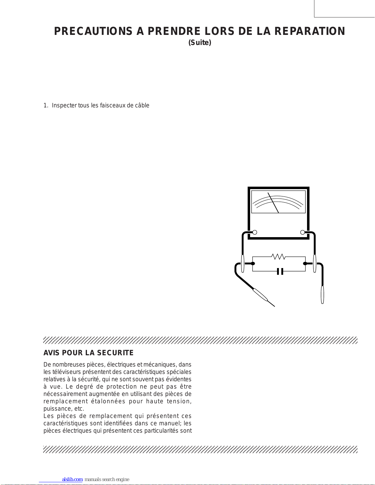
»Using to clip leads, connect a 1.5k ohm, 10 watt
resistor paralleled by a 0.15µF capacitor in series
with all exposed metal cabinet parts and a known
earth ground, such as electrical conduit or electrical
ground connected to earth ground.
»Use an AC voltmeter having with 5000 ohm per volt,
or higher, sensitivity to measure the AC voltage drop
across the resistor.
For continued protection, replacement parts must be
identical to those used in the original circuit. The use of
a substitute replacement parts which do not have the
same safety characteristics as the factory recommended
replacement parts shown in this service manual, may
create shock, fire, X-radiation or other hazards.
AC
VOLTMETER
IMPORTANT SERVICE SAFETY PRECAUTION
(Continued)
»Connect the resistor connection to all exposed metal
parts having a return to the chassis
(antenna, metal cabinet, screw heads, knobs and
control shafts, escutcheon, etc.) and measure theAC
voltage drop across the resistor.
AII check must be repeated with the AC line cord
plug connection reversed. (IF necessary, a non-
polarized adapter plug must be used only for the
purpose of completing these check.)
Any current measured must not exceed 0.5 milliamp.
Any measurements not within the limits outlined
above are indicative of a potential shock hazard and
corrective action must be taken before returning the
instrument to the customer.

25VT-K100
25VT-CK10
4
PRECAUTIONS A PRENDRE LORS DE LA REPARATION
Ne peut effectuer la réparation qu' un technicien spécialisé qui s'est parfaitement
accoutumé à toute vérification de sécurité et aux conseils suivants.
LIMITES DES RADIATIONS X ET DE LA
HAUTE TENSION
1. Tout le personnel réparateur doit être instruit des
instructions et procédés relatifs aux radiations X.
Le tube-image, seule source de rayons X dons les
téleviseurs transistorisés, n'émet pourtant pas de
rayons mesurables si la haute tension est maintenue
à un niveau préconisé dans la section "Vérification
de la haute tension".
C'est seulement quand la haute tension est excessive
que les rayons X peuvent entrer dans l'enveloppe du
tube-image y compris le conducteur de verre. Il est
important de maintenir la haute tension en-dessous
du niveau spécifié.
2. Il est essentiel que le réparateur ait sous la main un
voltmètre à haute tension qui doit être périodiquement
étalonné.
3. La haute tension doit toujours être maintenue à la
valeur de régime-et pas plus haute. L'opération à des
tensions plus élevées peut entraîner une panne du
tube-image ou du circuit à haute tension et, dans
certaines conditions, peut entraîner une radiation
dépassant les niveaux préscrits.
4. Quand le régulateur à haute tension fonctionne
correctement, il n'y a aucun problème de radiation
X. Chaque fois qu'un châssis couleurs est réparé, la
luminosité doit être examinée bout en contrôlant la
haute tension à l'aide d'un voltmètre pour s'assurer
que la haute tension ne dépasse pas la valeur
spécifiée et qu'elle soit correctement réglée.
5. Ne pas utiliser un tube-image autre que celui spécifié
et ne pas effectuer de modifications déconseillées
du circuit à haute tension.
6. Lors de la recherche des pannes et des mesures
d'essai sur un récepteur qui présente une haute
tension excessive, éviter de s'approcher inutilement
du récepteur.
Ne pas faire fonctionner le récepteur plus longtemps
que nécessaire pour localiser la cause de la tension
excessive.
AVERTISSEMENT
1. N'entreprendre aucune modification de tout circuit.
C'est dangereux.
2. Débrancher le récepteur avant toute réparation.
3. Les déversoirs thermiques à semi-conducteurs
peuvent présenter un danger de choc électrique
lorsque le réceqteur est en marche.
4. Le châssis de ce récepteur a deux systèmes de mise
à la terre qui sont séparés par un matériau isolant.
Le système de mise à la terre non-isolée (chaud) est
pour le circuit du régulateur de tension B+ et le circuit
de sortie horizontale. Le système de mise à la terre
isolé est pour les basses tensions C. C. B+ et le circuit
secondaire du transformateur de haute tension.
PRECAUTION:POUR LA
PROTECTION CONTINUE
CONTRE LES RISQUES
D'INCENDIE, REMPLACER LE
FUSIBLE PAR UN FUSIBLE DE
MEME TYPE 4A-125V.
4A 125V
REPARATION DU SYSTEME A HAUTETEN-
SION ET DUTUBE-IMAGE
Lors de la réparation de ce systéme,
supprimer la charge statique en branchant
une résistance de 10 kΩen série avec un fil
isolé (comme une sonde d'essai) entre la
mise à la terre du tube-image et le fil
d'anodel.(Le corden d'alimentation doit être
retiré de la prise murale.)
1. Il est à noter que le tube-image de ce récepteur est
intégralement protégé contre l'implosion.
2. Par mesure de sécurité, changer le tube-image pour
un tube du même numéro de type.
3. Ne pas lever le tube-image par son col.
4. Ne manipuler le tube-image qu'en porant des lunettes
incassables et qu'après avoir déchargé totalement
la haute tension.

25VT-K100
25VT-CK10
5
AC
VOLTMETER
VERIFICATIONS CONTRE L'INCEN-DIE ET
LE CHOC ELECTRIQUE
Avant de rendre le récepteur à l'utilisateur,effectuer
les vérifications suivantes.
»Toucher avec la sonde d'essai les pièces métalliques
exposées qui présentent une voie de retour au
châssis (antenne, coffret métallique, tête des vis,
arbres de commande et des boutons, écusson, etc.)
et mesurer la chute de tension CA en-travers de la
résistance.
Toutes les vérifications doivent être refaites après
avoir inversé la fiche du cordon d'alimentation. (Si
nécessaire, une prise d'adpatation non polarisée peut
être utilisée dans le but de terminer ces vérifications.)
Tous les courants mesurés ne doivent pas dépasser
0,5 mA.
Dans le cas contraire, il y a une possibilité de choc
électrique qui doit être supprimée avant de rendre le
récepteur au client.
12345678901234567890123456789012123456789012345678901234567890121234567890123456789012345678901212
1
234567890123456789012345678901212345678901234567890123456789012123456789012345678901234567890121
2
12345678901234567890123456789012123456789012345678901234567890121234567890123456789012345678901212
12345678901234567890123456789012123456789012345678901234567890121234567890123456789012345678901212
1
234567890123456789012345678901212345678901234567890123456789012123456789012345678901234567890121
2
12345678901234567890123456789012123456789012345678901234567890121234567890123456789012345678901212
AVIS POUR LA SECURITE
De nombreuses pièces, électriques et mécaniques, dans
les téléviseurs présentent des caractéristiques spéciales
relatives à la sécurité, qui ne sont souvent pas évidentes
à vue. Le degré de protection ne peut pas être
nécessairement augmentée en utilisant des pièces de
remplacement étalonnées pour haute tension,
puissance, etc.
Les pièces de remplacement qui présentent ces
caractéristiques sont identifiées dans ce manuel; les
pièces électriques qui présentent ces particularités sont
PRECAUTIONS A PRENDRE LORS DE LA REPARATION
(Suite)
1. Inspecter tous les faisceaux de câbles pour s'assurer
que les fils ne soient pas pincés ou qu'un outil ne soit
pas placé entre le châssis et les autres pièces
métalliques du récepteur.
2. Inspecter tous les dispositifs de protection comme
les boutons de commande non-métalliques, les
isolants, le dos du coffret, les couvercles ou blindages
de réglage et de compartiment, les réseaux de
résistance-capacité, les isolateurs mécaniques, etc.
3. S'assurer qu'il n'y ait pas de danger d'électrocution
en vérifiant la fuite de courant, de la facon suivante:
»Brancher le cordon d'alimentation directem-ent à une
prise de courant de 120V. (Ne pas utiliser de
transformateur d'isolation pour cet essai).
»A l'aide de deux fils à pinces, brancher une résistance
de 1,5 kΩ10 watts en parallèle avec un condensateur
de 0,15µF en série avec toutes les pièces métalliques
exposées du coffret et une terre connue comme une
conduite électrique ou une prise de terre branchée à
la terre.
»Utiliser un voltmètre CA d'une sensibilité d'au moins
5000Ω/V pour mesurer la chute de tension en travers
de la résistance.
1.5k ohm
10W
TO EXPOSED
METAL PARTS CONNECT TO
KNOWN EARTH
GROUND
AUX PIECES
METALLIQUES
EXPOSEES
Voltmètre CA
identifiées par la marque " å" et hachurées dans la
liste des pièces de remplacement et les diagrammes
schématiques.
Pour assurer la protection, ces pièces doivent être
identiques à celles utilisées dans le circuit d'origine.
L'utilisation de pièces qui n'ont pas les mêmes
caractéristiques que les pièces recommandées par
l'usine, indiquées dans ce manuel, peut provoquer des
électrocutions, incendies, radiations X ou autres
accidents.
BRANCHER A UNE
TERRE CONNUE
0.15µF
SONDE D'ESSAI

25VT-K100
25VT-CK10
6
TV SECTION POWER INPUT: 120 V AC 60 Hz
POWER RATING: 110W
PICTURE SIZE
Width: 63.4cm
Height: 58.8cm
Depth: 51.2cm
CONVERGENCE: Magnetic
SWEEP DEFLECTION: Magnetic
FOCUS: Hi-Bi-Potential Electrostatic
INTERMEDIATE FREQUENCIES
Picture IF Carrier Frequency: 45.75 MHz
Sound IF Carrier Frequency: 41.25 MHz
Color Sub-Carrier Frequency: 42.17 MHz (Nominal)
AUDIO POWER OUTPUT RATING: 1.3W (at 10% Distortion)
SPEAKER
Size: 8cm (3")P.M.,0.34 oz. Magnet
Voice Coil Impedance: 8 ohm at 400 Hz
VHF/UHFANTENNA INPUT IMPEDANCE: 75 ohm unbalanced
TUNING RANGES
VHF-Channels: 2 thru 13
UHF -Channels: 14 thru 69
CATV Channels: 1,14 thru 125 (EIA,Channel Plan)
VCR SECTION Format: VHS Standard
Video Recording System: Rotary Two-Head Helical Scanning
Number of Video Heads: 2 pcs.
Video Signal Standard: NTSC Color System
Tape Width: 12.7mm (1/2inch)
Tape Speed: (SP)33.35mm/sec (1.31i.p.s)
(LP)16.67mm/sec (0.66i.p.s)
Play back only
(EP)11.12mm/sec (0.44i.p.s)
Maximum Recording Time: (SP)160min (T-160)
(EP)480min (T-160)
Video Input: 0.5 to 2.0 Vp-p, 75 ohm unbalanced
Audio Input: -8dB, 47k ohm unbalanced (0 dB-0.775 Vrms)
Operating Temperature: 5°C to 40°C (41°F to 104°F)
Storage Temperature: -20°C to 60°C (-4°F to 140°F)
Specifications are subject to change without prior notice.
ELECTRICAL SPECIFICATIONS

25VT-K100
25VT-CK10
7
LOCATION OF USER'S CONTROL

25VT-K100
25VT-CK10
8
Location Of Control’s Buttons (Remote Control)
LOCATION OF USER'S CONTROL (Continued)

25VT-K100
25VT-CK10
9
1. Remove the 6 rear cover fixing screws and detach the rear cover.
2. Take out the anode cap, CRT PWB, connectors K,M and RC, coating ground SP chip, fixing screws and others.
3. Remove the 2 main PWB fixing screws and take out the main PWB unit and the VCR unit.
4. Remove the 7 VCR fixing screws, and detach the shielding case.
DISASSEMBLY AND REASSEMBLY

25VT-K100
25VT-CK10
10
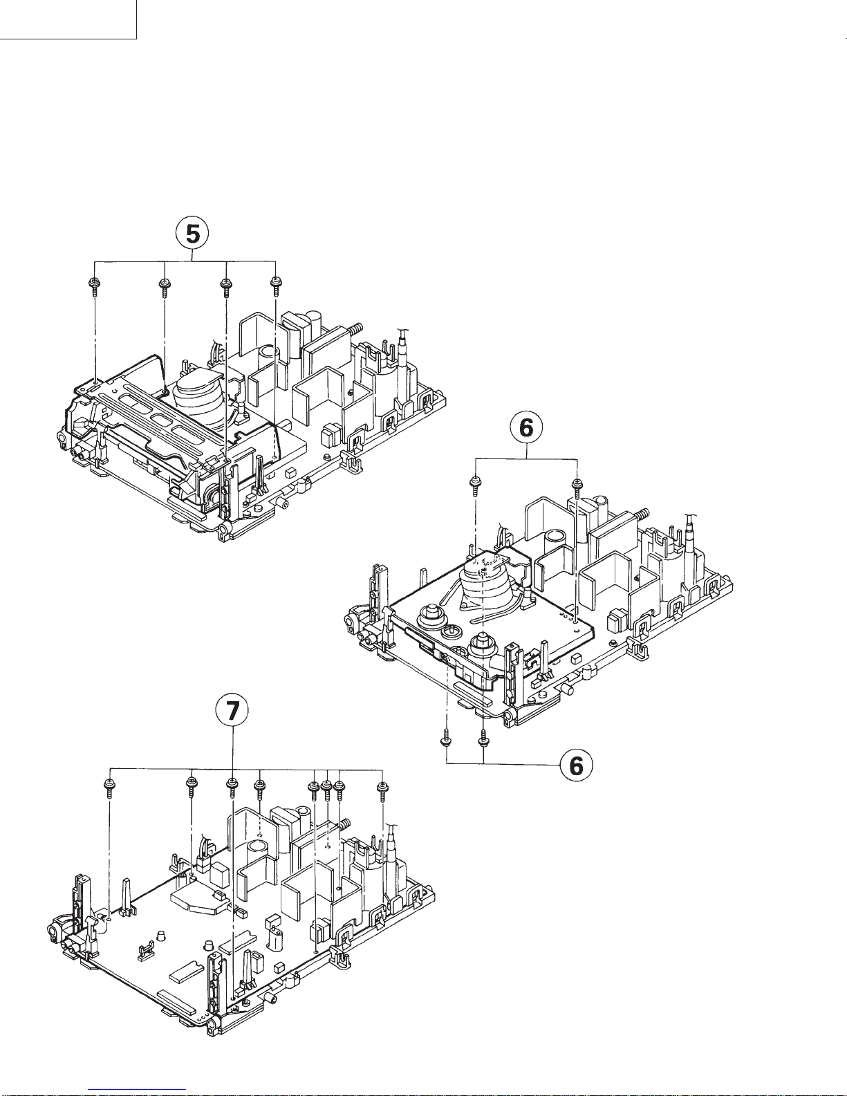
5. Remove the 4 cassette housing control fixing screws, and detach the cassette housing control.
6. Remove the 4 mechanism chassis fixing screws, and detach the mechanism chassis PWB.
7. Remove the 8 main PWB fixing screws, and detach the main PWB.
DISASSEMBLY AND REASSEMBLY (Continued)
This manual suits for next models
1
Table of contents
Other Sharp TV VCR Combo manuals

Sharp
Sharp 13VT-CR10 User manual

Sharp
Sharp 37VT-26H User manual

Sharp
Sharp VT-3428X User manual

Sharp
Sharp VT-G14 User manual

Sharp
Sharp 37VT-24H User manual

Sharp
Sharp VT-3418X User manual

Sharp
Sharp 13VT-N200 User manual

Sharp
Sharp 13VT-R100 User manual

Sharp
Sharp 13VT-R100 User manual

Sharp
Sharp VT-3448X User manual