Shakmat Mod Medusa User manual

Shakmat
Mod Medusa
Building Guide
12HP Eurorack Module Built & designed in E.U. www.shakmat.com

Table of contents
www.shakmat.com •
Preamble
Component list & necessary tools
PCB details
Assembly
4.1 Back
4.1.1
Power header (2x5 pin)
4.2 Front
4.2.1 Electrolytic capacitors
4.2.2
Jack connectors
4.2.3
Tacticle switches
4.2.5
Potentiometers
4.2.6
LED push buttons
4.2.7
LEDs
First startup routine
.................................................................................................................................. 2
................................................................................... 3
.............................................................................................................................. 4
................................................................................................................................... 5
.............................................................................................................................. 5
............................................................................... 5
.............................................................................................................................. 6
.................................................................................... 6
.............................................................................................. 7
............................................................................................. 8
................................................................................................ 9
......................................................................................... 10
............................................................................................................. 11-12
.............................................................................................................. 13
1.
2.
3.
4.
5.

www.shakmat.com •
02/13
Thank you for purchasing a Shakmat DIY kit !
We spare no effort in our kit packing process to prevent any mistakes or
missing parts. In this document as well, we do our best to describe the assem-
bly process in the most practical and comprehensive way. If by any chance
there is a missing/damaged part in your kit or if you have any suggestion, feel
free to contact us via shakmat.com.
We strongly advise you NOT to spill all the bags open and mix their
components. Some of them are virtually indistinguishable (like LEDs that
all appear clear when inactive). We recommend to only take the neccesary
component out of its bag, or to empty the bags in separate & marked contai-
ners. For each step, next to the component’s graphic representation, there is a
reference indicating where to find it (i.e. P1 for Pack 1, or LP for Loose Part).
The assembly process will be dramatically simplified if you follow the order
defined by this building guide. We tested various orders of steps before finding
the most convenient, and the one presented here is the best!
1. Preamble

www.shakmat.com •
03/13
Pack 1
3x 22 µF electrolytic capacitors
4x Tactile switch
4x Tactile switch caps
4x Green LEDs
2x Amber LED push button
Pack 2
1x 2x5 pin power header
4x White LEDs
4x Metal potentiometers
4x Metal potentiometer nuts
1x White LED push button
Pack 3
12x Jack connectors
12x Jack connectors nuts
4x Green/amber dual color LEDs
1x Green/red LED push button
2. Component list & necessary tools
Pink anti-static wrap
1x PCB
1x Front Panel
Loose parts
4x Black rubber knobs
1x Power cable
1x User manual
Necessay tools
Soldering iron
Solder
Cutting pliers
Masking tape

www.shakmat.com •
04/13
3. PCB details
PCB
Front & back

www.shakmat.com •
05/13
4. Assembly
Place the power header, short pin
side in the holes. We recommend
you only solder one of the pins. Then
reheat your soldered point and
simultaneously press the plastic part
of the header against the PCB until
it’s flat. Take off the soldering iron but
keep pressing. Avoid touching the
pins themselves because they will
become hot very quickly and move
out of alignment within their plastic
bracket. Once you are satisfied with
you placement, solder the remaining
pins.
4.1 Back
4.1.1 Power Header (2x5pin) P2

www.shakmat.com •
06/13
Flip the PCB and solder the three
22µF capacitors. You must pay
attention to the orientation of these
components. The long leg indicates
the positive side, therefore it has to
match the little dot on the PCB
silkscreen.
4.2 Front
4.2.1 Electrolytic capacitors (x3) P1
www.shakmat.com •
07/13
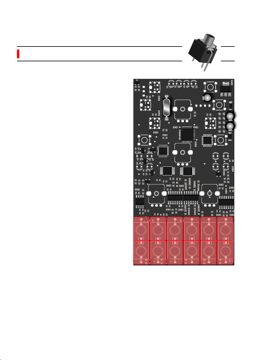
Place and solder the 12 jack connec-
tors. Be sure to lay them completely
flat on the PCB before soldering. If
those jacks aren’t perpendicular, the
front panel will be very hard to
mount.
If one of the jacks is not perfectly
perpendicular with the PCB, you can
reheat the pads and push it down
with your thumb to re-align.
4.2.2 Jack connectors (x12) P3
www.shakmat.com •
08/13
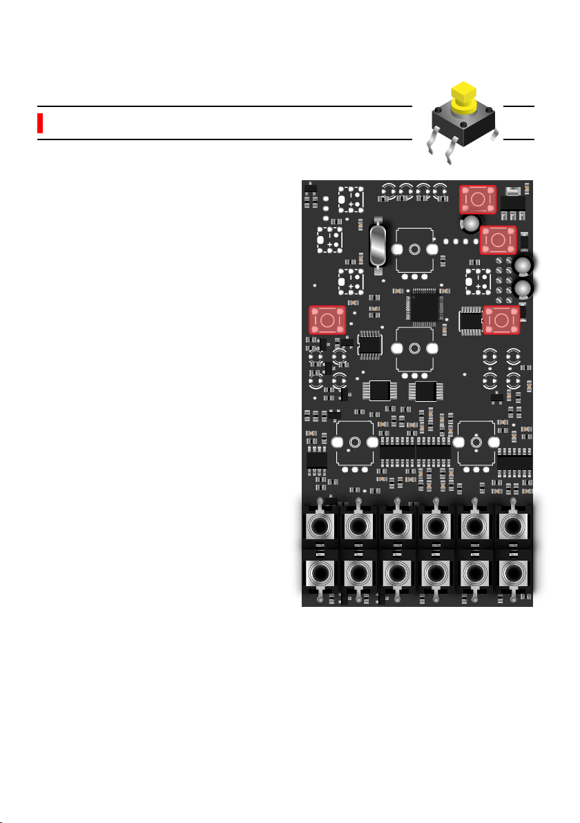
It’s very important to solder the four
push buttons flat with the PCB. If
they are crooked or not thoroughly
pushed through, the caps won’t pop
properly through the front panel and
the buttons will be hard to press.
4.2.3 Tactile switches (x4) P1

www.shakmat.com •
09/13
Before soldering, you will have to cut
a little metal piece off the top of each
potentiometer, as shown in the
picture. This little stud prevents the
front panel from sitting properly. Use
some small & sharp cutting pliers for
this task.
Then, place the 4 potentiometers on
the PCB. Mount the front panel and
tighten the potentiometers nuts (this
will ensure a proper placement of
the pots) and then solder them.
Once you have soldered everything,
remove the nuts, the front panel and
proceed to the next step.
4.2.4 Potentiometers & nuts (x4) P2
Cut!
4x
Other manuals for Mod Medusa
1
Table of contents
Other Shakmat Synthesizer manuals


