
SEW-Eurodrive CMP Series Operating instructions
*26877090_0322*
Drive Technology \ Drive Automation \ System Integration \ Services
Addendum to the Operating
Instructions
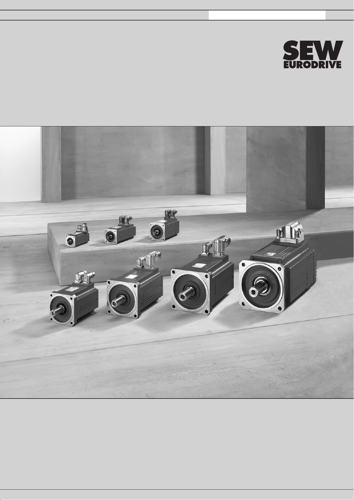
CMP.. Servomotors with MOVILINK® DDI Interface
CMP50 – CMP100
Edition 03/2022 26877090/EN

SEW-EURODRIVE—Driving the world

Table of contents
Addendum to the Operating Instructions – CMP.. Servomotors with MOVILINK® DDI Interface 3
Table of contents
1 General information.................................................................................................................. 4
2 Motor structure ......................................................................................................................... 5
2.1 Basic structure ................................................................................................................5
2.2 Motor nameplates ...........................................................................................................6
2.3 Type designation example ..............................................................................................7
2.4 Type code for MOVILINK®DDI interface identification ..................................................7
3 Designs and options ................................................................................................................ 8
3.1 Synchronous servomotors ..............................................................................................8
3.2 Mechanical attachments .................................................................................................8
3.3 Temperature sensor/temperature detection....................................................................8
3.4 Encoders.........................................................................................................................8
3.5 Connection options .........................................................................................................8
4 Electrical installation.............................................................................................................. 10
4.1 Information on connector connection............................................................................10
4.2 Connection with plug connectors ..................................................................................12
4.3 Connecting the plug connectors – single-cable technology with SD1/SDB with brake......
19
4.4 Connecting the motor and the encoder system with a terminal box .............................22
5 Cables for MOVILINK® DDI..................................................................................................... 30
5.1 Hybrid cable with connector on the motor side, open end on the inverter side ............31
5.2 Hybrid cable with open end on the motor side, open end on the inverter side .............31
5.3 Hybrid cable with connector on the motor side, connector on the inverter side............32
5.4 Hybrid cable with open end on the motor side, connector on the inverter side ............32
5.5 Coaxial cable with connector on the motor side, open end on the inverter side...........33
5.6 Cable tables ..................................................................................................................34
6 Cable connection.................................................................................................................... 37
6.1 Connection of motor/brake motor cable ../SD...............................................................37
7 Cable specifications............................................................................................................... 41
7.1 Fixed installation ...........................................................................................................41
7.2 Cable carrier installation ...............................................................................................43
8 Technical data of encoders ................................................................................................... 46
9 Technical data for brake control BG.Z, BS.Z, B................................................................... 47
9.1 Functional description ...................................................................................................47
9.2 Technical data...............................................................................................................47
10 Dimension sheets................................................................................................................... 49
10.1 Key to the dimension sheets.........................................................................................49
10.2 CMP.. dimension sheets ...............................................................................................50
26877090/EN – 03/2022

1General information
Addendum to the Operating Instructions – CMP.. Servomotors with MOVILINK® DDI Interface
4
1 General information
INFORMATION
The differences between the motors with the MOVILINK®DDI interface and the stan-
dard CMP.. motors are described in this document.
This document applies as a supplement to the "Synchronous servomotors CMP40–
CMP112, CMPZ71 – CMPZ100" operating instructions. The operating instructions
are still valid.
26877090/EN – 03/2022
2
Motor structure
Basic structure
Addendum to the Operating Instructions – CMP.. Servomotors with MOVILINK® DDI Interface 5
2 Motor structure
2.1 Basic structure
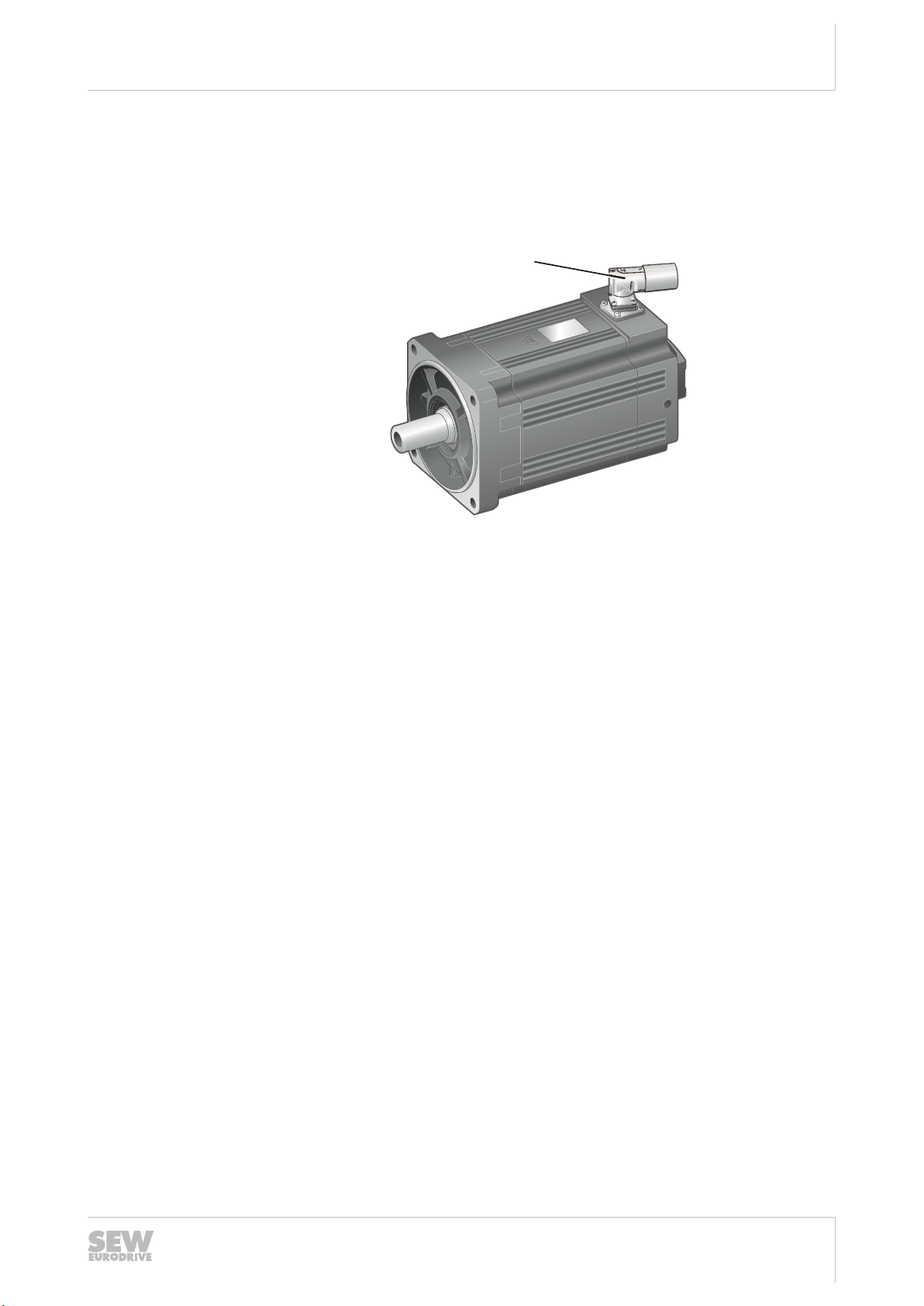
The following figure shows an example of a CMP.. servomotor with
MOVILINK® DDI interface:
[1]
29017423115
[1] Hybrid plug connector
26877090/EN – 03/2022
2Motor structure
Motor nameplates
Addendum to the Operating Instructions – CMP.. Servomotors with MOVILINK® DDI Interface
6
2.2 Motor nameplates
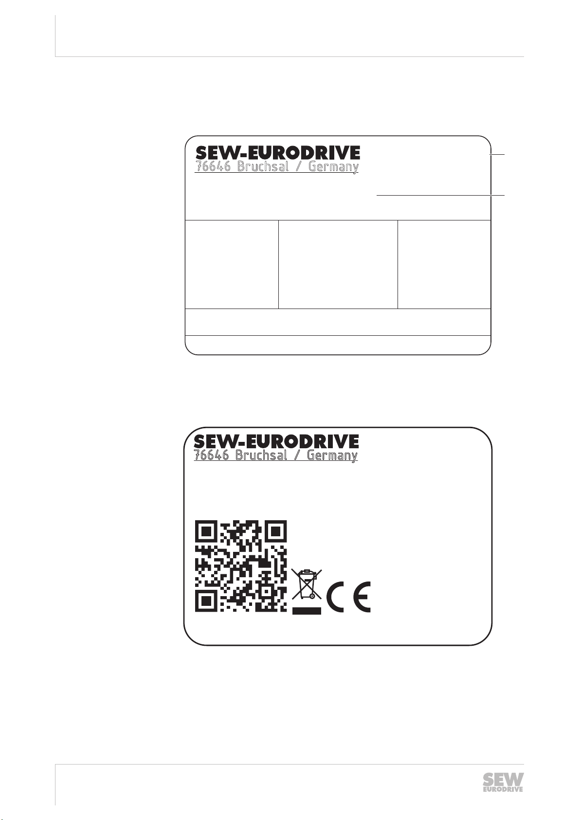
The following graphics show the nameplates of a CMP.. servomotor with the
MOVILINK® DDI interface as an example:
[1]
[2]
CMP50S/DI/PK/AZ4Z/SD1
01.123456789.0001.21
Mo 1.3 Nm
Mpk 5.2 Nm
Io 1.32 A
Imax 7 A
Usys 400 V
IM B5
IP 65
kg 2.213
Th.Kl. (F)
TENV
VTnC 0-4500 r/min
n max 4500 r/min
Up 281 V
Ta -20..40 °C
3~IEC60034 22935908 Made in Germany
DI0E00
Jahr2021
9007232620639243
[1] MOVILINK®DDI interface
[2] Type designation
CMP50S/DI/PK/AZ4Z/SD1
01.123456789.0001.21
nur Umrichterbetrieb 22936149
9007232620646411
26877090/EN – 03/2022
2
Motor structure
Type designation example
Addendum to the Operating Instructions – CMP.. Servomotors with MOVILINK® DDI Interface 7
2.3 Type designation example
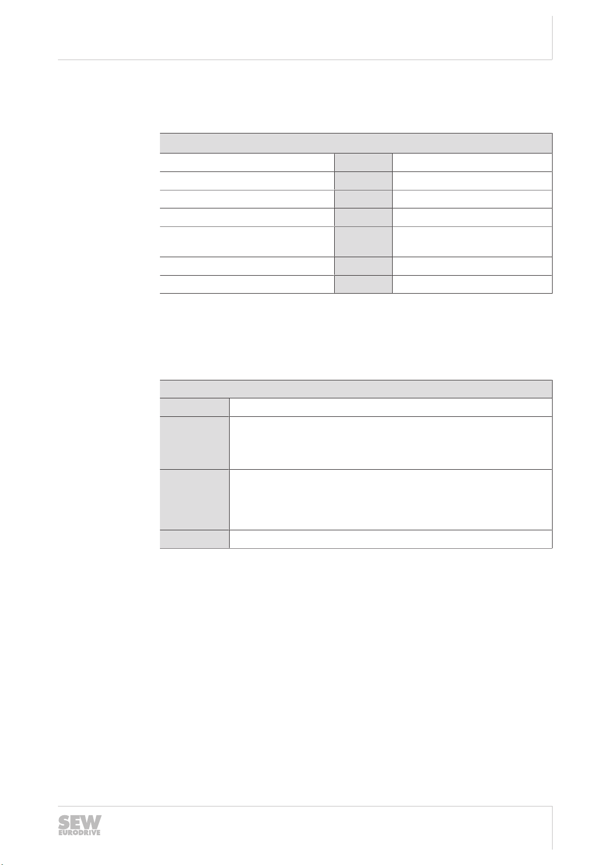
The following table shows the example of a type designation:
Example: CMP50S/BK/DI/PK/AZ4Z/SD1
Synchronous servomotor CMP50 Flange-mounted motor size 50
Length S Short
Mechanical attachments /BK BK holding brake
Motor option digital interface /DI MOVILINK® DDI
Standard equipment temperature
sensor
/PK PK temperature sensor
Encoder motor option /AZ4Z Multi-turn absolute encoder
Connection motor option /SD1 SD1 hybrid connector
2.4 Type code for MOVILINK®DDI interface identification
Type code
for
MOVILINK®
DDI
interface
identificatio
n
The following diagram shows the structure of the MOVILINK®DDI interface identifica-
tion:
DI0C00
DI DI = MOVILINK®DDI
0 0 = No brake control via MOVILINK®DDI1)
1 = Brake control BS1Z via MOVILINK® DDI
2 = Brake control BG1Z via MOVILINK® DDI2)
C C = Extended electronic nameplate and temperature detection (mo-
tor, inverter)
E = Extended electronic nameplate, temperature detection of motor
and encoder data acquisition (motor, inverter)
00 Reserved
1) If a "0" (DI0..) has been selected in the 3rd digit of the DI type code, the motor may be combined with a
MOVIMOT® flexible decentralized inverter. In the case of a MOVIDRIVE® or MOVITRAC® control cabinet
inverter, an external brake rectifier must be used.
2) If a "2" (DI2..) has been selected in the 3rd digit of the DI type code, the motor may not be combined with
a MOVIMOT® flexible decentralized inverter. In the case of a MOVIDRIVE® or MOVITRAC® control cab-
inet inverter, an external brake rectifier may not be used.
26877090/EN – 03/2022
3Designs and options
Synchronous servomotors
Addendum to the Operating Instructions – CMP.. Servomotors with MOVILINK® DDI Interface
8
3 Designs and options
3.1 Synchronous servomotors
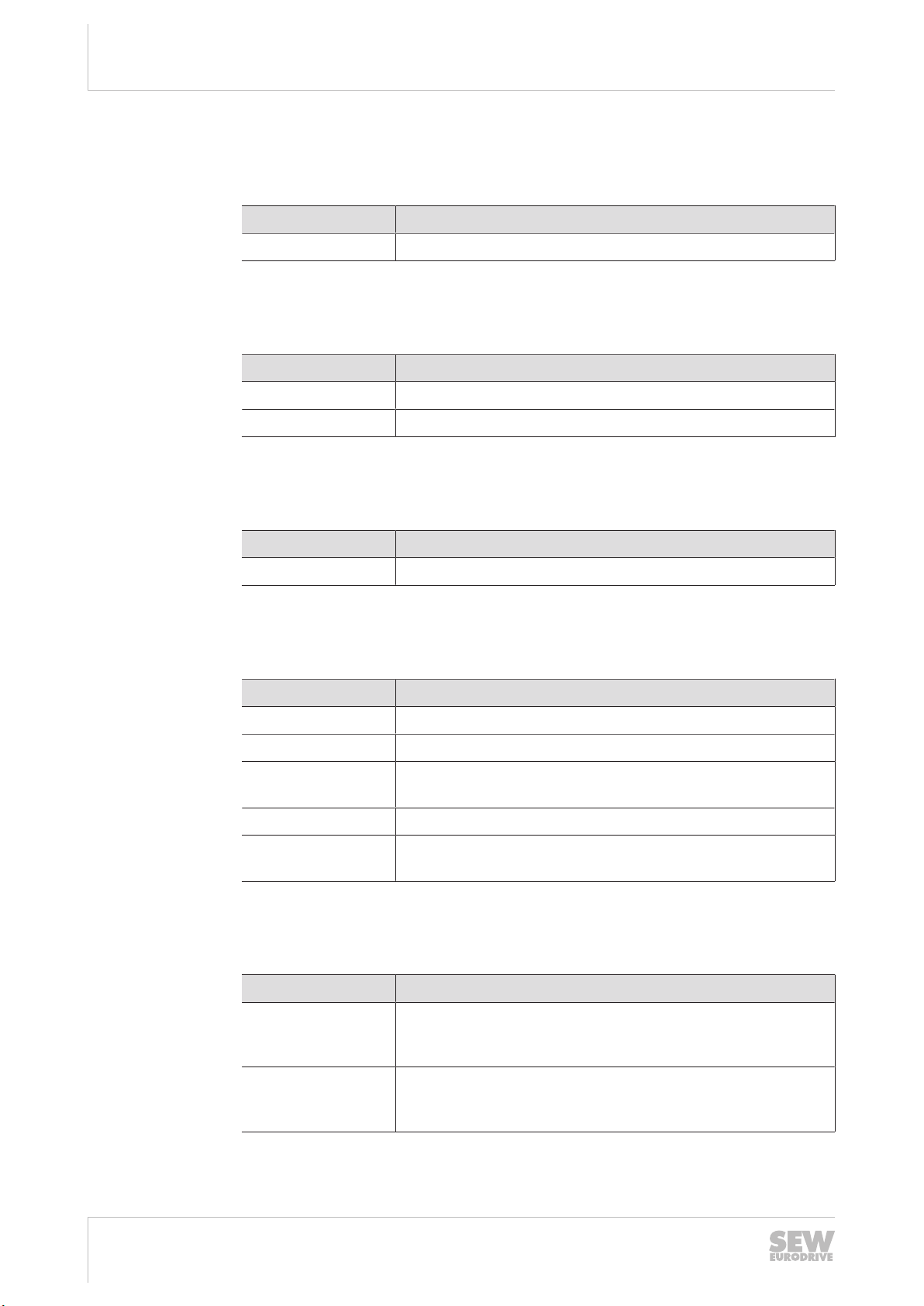
Designation
CMP.. Flange-mounted motor size 50 / 63 / 71 / 80 / 100
3.2 Mechanical attachments
Designation Option
/BK Permanent magnet brake for CMP50 – 63
/BP Holding brake for CMP71–100
3.3 Temperature sensor/temperature detection
Designation Option
/PK PT1000 temperature sensor
3.4 Encoders
Designation Option
– No encoder, (CMP50–100)
/EZ2Z Single-Turn encoder, MOVILINK® DDI, (CMP50–100)
/EZ4Z Single-Turn encoder, MOVILINK® DDI, high resolution,
(CMP50–63)
/AZ2Z Multi-Turn encoder, MOVILINK® DDI, (CMP50–100)
/AZ4Z Multi-Turn encoder, MOVILINK® DDI, high resolution,
(CMP50–63)
3.5 Connection options
Designation Description
/SD1 Motor connector, M23, only plug socket at the motor side, hy-
brid connector for motor, brake and communication
MOVILINK® DDI, (CMP50–100)
/SDB Motor connector, M40, only plug socket at the motor side, hy-
brid connector for motor, brake and communication
MOVILINK® DDI, (CMP50–100)
26877090/EN – 03/2022
3
Designs and options
Connection options
Addendum to the Operating Instructions – CMP.. Servomotors with MOVILINK® DDI Interface 9
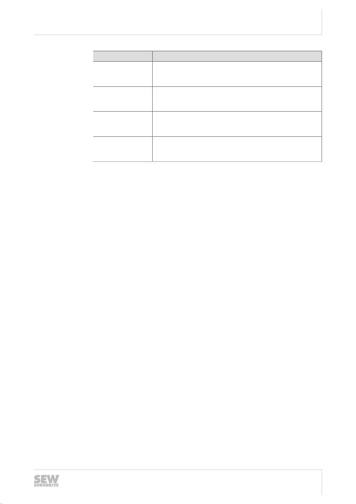
Designation Description
/KD Terminal box for CMP50 –100, hybrid cable for motor, brake
and encoder MOVILINK® DDI clampable,
(CMP50–100)
/KDD Terminal box for CMP80 – 100 with AZ2Z/EZ2Z/without en-
coder, clampable power connection, encoder connector, M23,
MOVILINK® DDI pluggable
/SMCD Motor power connector, M58; encoder connector
MOVILINK® DDI, M23, (CMP100 with AZ2Z/EZ2Z/without en-
coder)
/SBCD Brakemotor power connector, M58; encoder connector
MOVILINK® DDI, M23, (CMP100 with AZ2Z/EZ2Z/without en-
coder)
26877090/EN – 03/2022

4Electrical installation
Information on connector connection
Addendum to the Operating Instructions – CMP.. Servomotors with MOVILINK® DDI Interface
10
4 Electrical installation
4.1 Information on connector connection
With SD1 and SDB, the cable is introduced via an adjustable right-angle connector.
SEW‑EURODRIVE recommends aligning the right-angle connector with the mating
connector plugged in.
NOTICE
Damage to the right-angle connector can occur in case of rotation without mating
connector.
Damage to the plug connector and the sealing surface can occur.
• Adjust the right-angle connector only while the mating connector is plugged in.
• If you do not have a mating connector at hand, do NOT use pliers to adjust the
right-angle connector.
NOTICE
Potential damage to the right-angle connector.
Possible damage to property.
• Do not align the right-angle connector frequently.
INFORMATION
• Comply with the permitted bending radii of the cables.
• When using low-capacity trailing cables, the bending radii are larger than for the
previously used standard cables.
• SEW‑EURODRIVE recommends the use of low-capacity cables.
• Use cables with a permitted continuous operating temperature of minimum 80°C.
INFORMATION
The connector should only be rotated to install and connect the motor. Do not turn
the plug connector regularly once it has been installed.
26877090/EN – 03/2022
Other manuals for CMP Series
1
This manual suits for next models
2
Table of contents
Other SEW-Eurodrive Servo Drive manuals

SEW-Eurodrive
SEW-Eurodrive CMP40 - 112 User manual

SEW-Eurodrive
SEW-Eurodrive CMDV55M User manual

SEW-Eurodrive
SEW-Eurodrive CM3C Series User manual

SEW-Eurodrive
SEW-Eurodrive MOVITRAC LTX Operating instructions

SEW-Eurodrive
SEW-Eurodrive DR Series User manual

SEW-Eurodrive
SEW-Eurodrive Movidrive MDX60B User manual

SEW-Eurodrive
SEW-Eurodrive CMP ELVCD User manual

SEW-Eurodrive
SEW-Eurodrive CM3C Series User manual

SEW-Eurodrive
SEW-Eurodrive CMP Series Operating instructions

SEW-Eurodrive
SEW-Eurodrive CMP40 User manual


