DAL 1965
Pag. 3/18
1
230V
3 x 1,5
4 x 0,5
2 x 0,5
4 x 0,5
4 x 1,5
4 x 1,5
2 x 0,5
3 x 0,5
RG58 2 X 1,5
1
2
4
55
3
6
MT/30/2 MT/38/1
Power supply 230 V~ ±10% 50/60 Hz 230V~ ±10% - 50/60 Hz
Max. leaf length 3,00 m 2,00 m
Max. leaf weight 300 kg 200 kg
Max. opening angle 110° 110°
Max. absorption 1,6 A 1,6 A
Power 150 W 150 W
Max. torque 180 Nm 120 Nm
Max. thrust 1200 N 1200 N
Angular speed 0,09 rad/s 0,11 rad/s
Opening time for 90° 17 s 17 s
Motor force adjusted: via power supply voltage control
Capacitor 12,5µF 12,5µF
Motor thermal protection 150° 150°
Protection rating IP55 IP55
Operating temperature -20°C ÷ +60°C -20°C ÷ +60°C
Dimensions 950 x 115 x 80 mm 750 x 115 x 80 mm
Weight 9 kg 7,5 kg
4 M/10 electric key
5 Pair of P/10 photocells
6 RZ/20 F Flashing light with antenna
SYSTEM TYPE
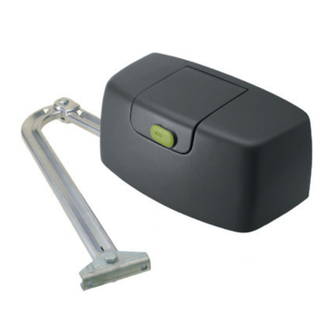
1 MT/30/2, MT/38/1 gearmotor
2 CR/41 electronic control unit with built-in receiver
3 OG/62 2-channel minitransmitter
Advice for wiring up in non-specialised environments.
1. Fit an omnipolar switch upstream of the system, choosing one with a gap of at least 3mm between the contacts. Or,
alternatively, use a 10Athermal magnetic circuit breaker.
2. Always make connections, of any type, with the system disconnected from the power supply, i.e. with the main switch
set to OFF (symbol “0”). The control unit, in particular, must never be connected to the power supply either during the
wiring up, or when fitting any expansion boards.
3. The following cables must be used for installation of the system:
22
- for the control unit, motor and electric lock power supplies: 1.5mm section for lengths of up to 19m, 2.5mm section
for lengths of up to 31m,
22
- for the flashing light: 0.75mm section for lengths of up to 3m, 1.5mm section for lengths of up to 19m,
- for the low voltage and current lines, (e.g. for the photocells, control buttons, electromechanical key, sensitive
22
edges and other safety devices: 0.5mm section for lengths of up to 50m, 0.75mm section for lengths of up to 100m.
4. Wire up the earth connection in compliance with legal provisions.
GEARMOTOR TECHNICAL SPECIFICATIONS
The technical data refer to an ambient temperature of 25°C with intermediate force setting.
Lower operating temperatures or higher stress levels could require increased force settings. The opposite applies
for higher temperatures or lower stress levels.
KIT/30-39F I E