Seneca Z-SG User manual

Page 1
MI003790
MI002636
SENECA s.r.l.
Via Austria, 26 –35127 –PADOVA –ITALY
Tel. +39.049.8705355 –8705359 Fax. +39.049.8706287
Web site: www.seneca.it
This document is property of SENECA srl. Duplication and reproduction are forbidden, if not authorized. Contents of the present
documentation refers to products and technologies described in it. All technical data contained in the document may be modified
without prior notice Content of this documentation is subject to periodical revision.
To use the product safely and effectively, read carefully the following instructions before use. The product must be used only for the
use for which it was designed and built. Any other use must be considered with full responsibility of the user. The installation,
implementation and set-up is allowed only for authorized operators; these ones must be people physically and intellectually suitable.
Set up must be performed only after a correct installation and the user must perform every operation described in the installation
manual carefully. Seneca is not considered liable of failure, breakdown, accident caused for ignorance or failure to apply the indicated
requirements. Seneca is not considered liable of any unauthorized changes. Seneca reserves the right to modify the device, for any
commercial or construction requirements, without the obligation to promptly update the reference manuals.
No liability for the contents of this documents can be accepted. Use the concepts, examples and other content at your own risk. There
may be errors and inaccuracies in this document, that may of course be damaging to your system. Proceed with caution, and although
this is highly unlikely, the author(s) do not take any responsibility for that. Technical features subject to change without notice.
USER MANUAL
Z-SG / Z-SG-L
Advanced Digital
Strain gauge converter

USER MANUAL –Z-SG
2
Date
Revision
Notes
15/04/2016
4
New revision
28/09/2016
5
Correct example at chapter 11.2
21/10/2019
6
Edited chapter: Calibration with a standard weight
Fix Analog Input Features

USER MANUAL –Z-SG
3
Table of Contents
1. GLOSSARY..................................................................................................................5
2. GENERAL CHARACTERISTICS..................................................................................5
3. FEATURES...................................................................................................................5
4. LEDS FOR SIGNALLING.............................................................................................7
5. LOAD CELL: 4 OR 6 WIRES CONNECTION ..............................................................8
6. ANALOG OUTPUT (ONLY Z-SG MODEL) ..................................................................9
7. “STABLE WEIGHT” CONDITION................................................................................9
8. DIGITAL INPUT / DIGITAL OUTPUT...........................................................................9
9. DIP-SWITCHES TABLE .............................................................................................10
10. MEASURE CALIBRATION WITH MODBUS REGISTERS.....................................12
10.1. CALIBRATION WITH EASY SETUP ...................................................................................................................12
10.2. CALIBRATION WITH A STANDARD WEIGHT ...................................................................................................13
10.3. CALIBRATION WITHOUT A STANDARD WEIGHT ............................................................................................13
11. MEASURE CALIBRATION WITHOUT MODBUS REGISTERS.............................14
11.1. CALIBRATION WITH A STANDARD WEIGHT USING THE CALIBRATION BUTTON.............................................14
11.2. CALIBRATION WITHOUT A STANDARD WEIGHT USING THE CALIBRATION BUTTON......................................15
12. EASY-SETUP..........................................................................................................17
13. MODBUS RTU PROTOCOL ...................................................................................17
13.1. Modbus function code supported .................................................................................................................18
13.2. Modbus RTU Register table...........................................................................................................................18

USER MANUAL –Z-SG
4
Seneca Z-SG / Z-SG-L
CAUTION!
UNDER ANY CIRCUMSTANCES, SENECA S.R.L. OR ITS SUPPLIERS SHALL NOT BE RESPONSIBLE FOR
LOSS OF RECORDING DATA/INCOMES OR FOR CONSEQUENTIAL OR INCIDENTAL DAMAGE DUE
TO NEGLECT OR RECKLESS MISHANDLING OF Z-SG / Z-SG-L, EVEN THOUGH SENECA IS WELL
AWARE OF THESE POSSIBLE DAMAGES.
SENECA, ITS SUBSIDIARIES, AFFILIATES, COMPANIES OF THE GROUP, ITS SUPPLIERS AND
RETAILERS SHALL NOT GUARANTEE THAT THE FUNCTIONS WILL SATISFY COMPLETELY
CUSTOMER’S EXPECTATIONS OR THAT Z-SG / Z-SG-L, THE FIRMWARE AND THE SOFTWARE SHALL
HAVE NO ERRORS OR WORK CONTINUOUSLY.

USER MANUAL –Z-SG
5
1. Glossary
Modbus RTU
An open protocol for the serial communications developed by Modicon Inc. (AEG Schneider Automation
International S.A.S.). Simple and robust, it has since become a de facto standard communication protocol.
For more info http://www.modbus.org/specs.php
2. General characteristics
ADC with 24bit resolution
4 wires or 6 wires load cell measure mode
Compression and Traction or only compression load mode
NR 1 analog output configurable in Current or Voltage mode (only Z-SG model)
Load cell sensitivity configurable from +-1mV/V to +-64mV/V or virtually every sensitivity
Measure resolution configurable
RS232 and RS485 port with Modbus RTU protocol
Configurable Moving average filtering
Digital input for Tare acquisition (only Z-SG model)
General purpose Digital input or Digital output (only Z-SG-L model)
Digital output with one configurable weight threshold or “stable measure” condition
Modbus Station address and baud-rate configurable by Dip-Switches
3. Features
ANALOG INPUT
Number
1 (for one load cell: + Excitation, - Excitation, +Sense, - Sense, +
Signal, - Signal)
Resolution
24bits
Sampling frequency
Configurable between: 12.53Hz; 16.65Hz; 24.82Hz; 37.59Hz;
49.95Hz; 50.57Hz; 74.46Hz; 151.71Hz
Rejection
50Hz or 60Hz
ANALOG OUTPUT (only Z-SG model)
Number
1
Accuracy
0.1% of output scale range
USER MANUAL –Z-SG
6
Response time (10%-
90%)
5ms
Voltage-type OUT
Output scale range configurable between: 0..5V or 0..10V by Dip-
Switches. Minimum resistance that can be connected: 2 k
Current-type OUT
Output scale range configurable between: 0..20mA or 4..20mA by
Dip-Switches. Max resistance that can be connected: 500
LOAD CELLS
A load cell or more load cells (if they are parallel-connected) can be connected to the Z-SG
module.
Load impedance
Minimum impedance that can be connected: 87 . This value can
be equivalent impedance of more parallel-connected load cells.
For example: up to 4 load cells (if each cell has input impedance:
350), up to 8 load cells (if each cell has input impedance: 1000)
Cell sensitivity
Configurable between: ±1mV/V; ±2mV/V; ±4mV/V; ±8mV/V;
±16mV/V; ±32mV/V; ±64mV/V by Dip-Switches.
From +-1mV to virtually infinity from Modbus Registers.
Internal load cell
voltage supply
the #7 screw terminal (+Excitation) powers 5Vdc with reference to
the #10 screw terminal (-Excitation). The #8 screw terminal
(+Sense) reads “+Excitation”, the #11 screw terminal (-Sense)
reads “-Excitation”
CONNECTIONS
RS485 interface
IDC10 connector
RS232 interface
Jack stereo 3.5mm connector: plugs into COMport
PROTECTION
This module provides inputs protection against the ESD (up to 4kV)
for every screw terminals
1500 Vac ISOLATIONS
Between: power supply, ModBUS RS485 and analog output, analog
input, digital input/output

USER MANUAL –Z-SG
7
POWER SUPPLY
Supply voltage
10 –40 Vdc or 19 –28 Vac ( 50Hz - 60Hz)
Power
consumption
Max: 2W
The power supply transformer necessary to supply the module must be comply with EN60742
(Isolated transformers and safety transformers requirements).
To protect the power supply, is recommended to install a fuse.
4. LEDs for signalling
In the front-side panel there are 4 LEDs and their state refers to important operating conditions
of the module.
LED
LED status
Meaning
PWR
Constant light
The power is on
ERR
Blinking light
See “Setting by calibration button”
Turn off after 3
seconds
See “Setting by calibration button”
RX
Constant light
Verify if the bus connection is corrected
Blinking light
The module received a RS485 data packet
USER MANUAL –Z-SG
8
TX
Blinking light
The module sent a RS485 data packet
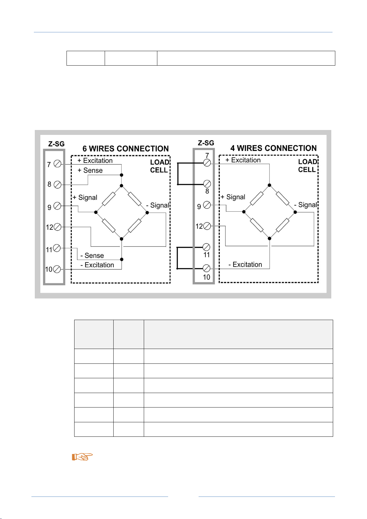
5. Load Cell: 4 or 6 Wires Connection
The Load Cell can be connected in 6 or 4 wires:
Input
Screw
terminal
Meaning
+ Excitation
7
Load cell power (+)
+ Sense
8
Reading of load cell power (+)
+ Signal
9
Load cell output signal (+)
- Signal
12
Load cell output signal (-)
- Sense
11
Reading of load cell power (-)
- Excitation
10
Load cell power (-)
To connect the Z-SG / Z-SG-L to load cell in 4-wires mode:
- short-circuit screw terminal 7 to screw terminal 8;

USER MANUAL –Z-SG
9
- short-circuit screw terminal 10 to screw terminal 11.
Use shielded cables for connections.
6. ANALOG OUTPUT (ONLY Z-SG MODEL)
The Analog output can be configured in Voltage or Current mode:
”V” means voltmeter, “A” means amperemeter.
The Analog output is proportional to the net weight measure.
The Analog Output 0% and 100% can be fully configurable.
7. “STABLE WEIGHT” CONDITION
Z-SG / Z-SG-L module allows to detect when a weight measure is stable:
weight stability information is available through 40066 Modbus register (bit Nr 4) or through
digital output.
In particular, a weight measure is stable:
If the net weight measure variation (reg.40064-40065), in a given time interval (“delta time”,
reg.40058), is less than weight interval (“delta weight”, reg.40056-40057).
8. DIGITAL INPUT / DIGITAL OUTPUT

USER MANUAL –Z-SG
10
”V” means equivalent voltage generator.
Z-SG / Z-SG-L module can be configured in digital input mode or (in alternative) in digital output
mode only by Dip-Switch.
In the Z-SG model the digital input can be used for:
-Acquire a tare value
-Alternative for the calibration button
in the Z-SG-L model the digital input can be used for acquire a general purpose input.
Digital output allows to open/close a opto-isolated contact
In Z-SG/Z-SG-L model the digital output can be controlled by the firmware with this
configurations:
-gross weight is greater than load cell end scale
-weight is stable and net weight is greater than Threshold
-weight is stable
In the Z-SG-L model the digital output can also be controlled from modbus register.
9. Dip-switches table
In the following tables:
box without circle means Dip-Switch=0 (OFF state);
box with circle means Dip-Switch=1 (ON state).
Other manuals for Z-SG
3
This manual suits for next models
1
Table of contents
Other Seneca Media Converter manuals

Seneca
Seneca S107USB User manual

Seneca
Seneca Z-MBus User manual

Seneca
Seneca Z-SG3 User manual

Seneca
Seneca Z-SG User manual

Seneca
Seneca Z-SG User manual

Seneca
Seneca S117P1 User manual

Seneca
Seneca Z109REG-BP User manual

Seneca
Seneca Z-SG2 User manual

Seneca
Seneca Z-8TC-SI User manual

Seneca
Seneca Z201 User manual

Seneca
Seneca Z109REG-BP User manual

Seneca
Seneca K109UI User manual

Seneca
Seneca ZC-SG User manual

Seneca
Seneca EASY-USB User manual

Seneca
Seneca Z Series User manual

Seneca
Seneca Z204-1 User manual

Seneca
Seneca Z111 User manual

Seneca
Seneca Z-4RTD2-SI User manual

Seneca
Seneca Z-SG3 User manual

Seneca
Seneca Z-4RTD2 User manual


