SCHlabs HMP 1-B User manual

www.schlabs.com.ar
HMP 1-B
Model:
0120.05
Rev doc: 00
Electronic throttle tester
Users Manual
Connect ng power supply Pág. 2
Connect ng probes Pág. 2
Select proper probes Pág. 2
Body Throttle test Pág. 3
Pedal (apps) test Pág. 4
Analog Sensor Test Pág. 5
Oxygen/Lambda Test Pág. 5
Voltmeter Pág. 6
Battery test Pág. 6
Frequency meter and PWM meter Pág. 7
Ohmmeter Pág. 7
NTC test Pág. 8
Log c Probe Pág. 8
Crankshaft (CKP) sensor Pág. 9
IAC valve test ng Pág. 9
Generat ng hall CKP pulses Pág. 10
Generat ng analog voltage Pág. 10
Setup Pág. 10
Pre assembled cables and new cables Pág. 11
Reports on screen Pág. 13
Determ n ng Common fa ls Pág. 14
Troubleshoot ng Pág. 14
Short c rcu ts and General warn ngs Pág. 15
Warranty Pág. 15
1/16

Connecting power supply
The dev ce need for work 12Vdc cont nuous. Become w th 2
cocodr les to allow connect to car battery.
DO NOT USE battery chargers w thout a car battery.
Connecting terminal block
Once you choose the appropr ate cable you must plug n the
rear connector.
Use
-Preassembled cables for Throttle body's and Pedals
-S ngle cable on TPS2 for analog voltage generat on
-S ngle cable on TPS1 for other measurement
Selecting test type
When you plug the power supply (12v) you w ll see the
pr nc pal menu on screen.
Us ng The keys “+” and “-” you
w ll see d fferent tests.
When you see nto the screen the
r ght test, press OK.
2/16

Testing of electronic throttle
1) THE ENGINE MUST BE STOPPED. The eng ne can be
damaged f s over accelerated mov ng the butterfly manually.
2) Choose the appropr ate cable, check the connect ons,
spec ally the co l connect on n the cable A & cable B.
3) Plug 12Vdc and throttle body and choose “throttle” on the
menu, then press ”OK”.
Into the screen you w ll see 4 nformat ons s m lar to the mage:
A=Max D fference
B=Motor Co l current
C=TPS1 pos t on ( n %)
D=TPS2 pos t on ( n %)
4) Us ng “+” and “-” move the butterfly from m n to max
open ng. If you press both the butterfly w ll move alone.
The HMP1 w ll check the cons stency between TPS1 & TPS2
and w ll show the d fference between deal measure and real
measure. Th s s the most mportant data that ECU look.
The max d fference tolerated by the ECU s d fferent
form car to car but generally s acceptable a value under 5%.
3/16
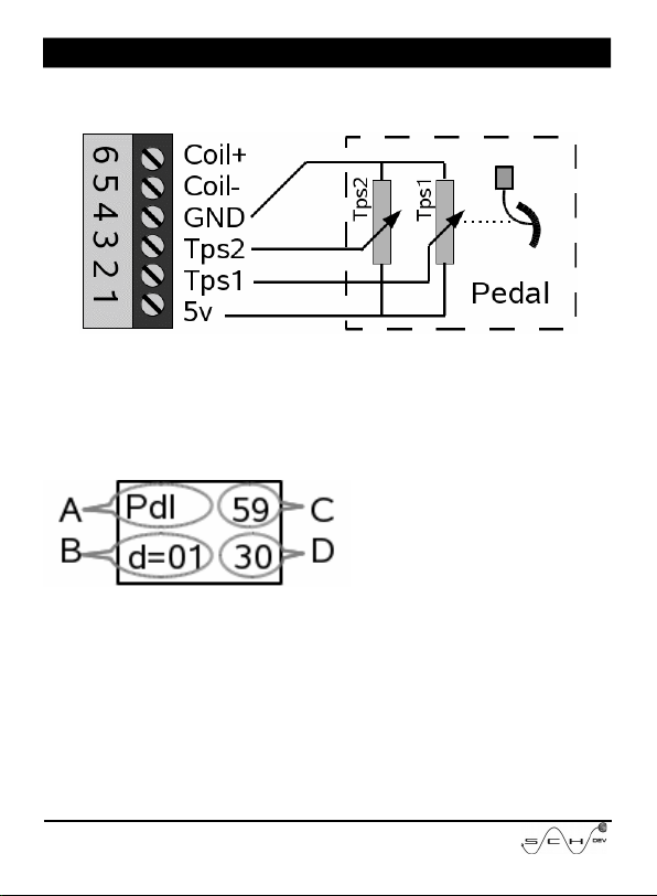
Electronic Pedal test
Connect the pedal us ng the r ght connector or use the
crocod les to connect follow ng mage.
After that you must press “+” and “-” keys unt l you see
PEDAL on screen, and press “OK”.
Now on the screen you w ll see 4 nformat ons l ke the bellow
mage:
A=You are test ng a Pedal
B=D fference between C y D
C=TPS1 pos t on ( n %)
D=TPS2 pos t on ( n %)
To test t, allways w th the eng ne off, press slowly up to reach
full press. Avo d fast movements.
The HMP1 w ll calculated the coherence between TPS1 and
TPS2 and w ll shot the d fference between deal relat onsh p
and real relat onsh p.
Press ng the OK Button, you w ll come back to the pr nc pal
menu to perform another test.
4/16

Analog Sensor test
In the pr nc pal menu, press the keys “+” or “-” unt l you see
SENS AN on the screen, and press OK button.
You can test TPS, MAP, MAF and another sensors that have
0~5v. The result w ll show n percentage (unless you conf gure
volt)
Press ng “OK” button you w ll return to the pr nc pal menu.
Oxygen sensor test ( ambda)
Is poss ble measure oxygen sensor that have an output between
0-5v. The bottom bar w ll move from 0 to 1v, the voltage must
be ncome n p n of TSP1.
Into the pr nc pal menu, press the “+” or “-” keys unt l you see
LAMBDA nto screen, and press “OK”.
A) Lambda test
B) R chness bar
C) Incom ng Voltage
D)
5/16

Voltmeter
Into the pr nc pal menu, press the “+” or “-” keys unt l you see
VOLT nto screen, and press “OK”.
Is poss ble measure voltages com ng on TPS1 from 0 to 20V
but only after chosen voltmeter.
Note: as the voltmeter have not a so h gh mpedance can’t be
used to measure out of res st ve sensors l ke TPS.
A) Voltmeter
B) Voltage bar
C) Incom ng Voltage
D)
Battery test
Into the pr nc pal menu, press the “+” or “-” keys unt l you see
BATTERY nto screen.
The battery meter can measure the voltage from 7.4 up to 20
Volts. Out of these ranges you w ll see wrong values.
The HMP1 measure the actual voltage from battery more than
100 t mes at second. Also rem nder the m n and max voltage
reached by the car system.You can see n the report.
A) You are test ng BATtery
B) Graph c BAR
C) The actual voltage
D)
6/16

If you press “OK” you w ll see a l ttle report w th m n mum and
max mum, after that the HMP1 go to the pr nc pal menu.
Frequency and pwm meter
Into the pr nc pal menu, press the “+” or “-” keys unt l you see
Frec-Hz nto screen, and press “OK”.
W ll show frequenc es from 15 to 2000Hz that s showed n
Hertz. In the bottom l ne the pulse w dth s showed n
percentage (%). Only w ll be taken pulses from 3v to 20v.
A) Your measur ng Hertz
B) Pulse w dth
C) Actual Hertz
D) Actual w dth
Example and graph c of MAP Ford Measure:
1)Idle
2)Smooth accelerat on
3)Fast decelerat on
4)Fast Accelerat on
5)Smooth decelerat on
Ohmmeter
Into the pr nc pal menu, press the “+” or “-” keys unt l you see
OHM nto screen, and press “OK”.
You can measure the res stance between TPS1 and GROUND
w th relat ve accuracy from 50KΩ to 10Ω. Th s tool do not
pretend replace the tester
7/16

A) Are measur ng OHMs
B) Graph c Bar
C) Res stance measured
D)
The measures w ll showed on human format where a value of
10.000Ω w ll be showed as 10K.
NTC tester
At same way that ohmmeter measure the res stance from TPS1
and GROUND. But calculate and show the temperature n
Cels us or Fahrenhe t degrees.
In the ma n menu press + y – unt l see NTC and press OK.
A) Are test ng NTCs
B) NTC R0 a 25°c (77°f)
C) Res stance measured
D) Calculated Temperature
R0 s the value n ohms for NTC at 25°C(77°F). Ma nly th s
value s prov ded by manufacturer nto serv ce manual, but you
can check manually at amb ent temperature.
Use “+” y “-” for change R0 value. The res stances w ll showed
n human format
ogic probe
Allow determ ne f n a cable there are voltage, pulses, f s
connected or s mply unconnected. The measurement w ll be
done from TPS1 nput.
8/16
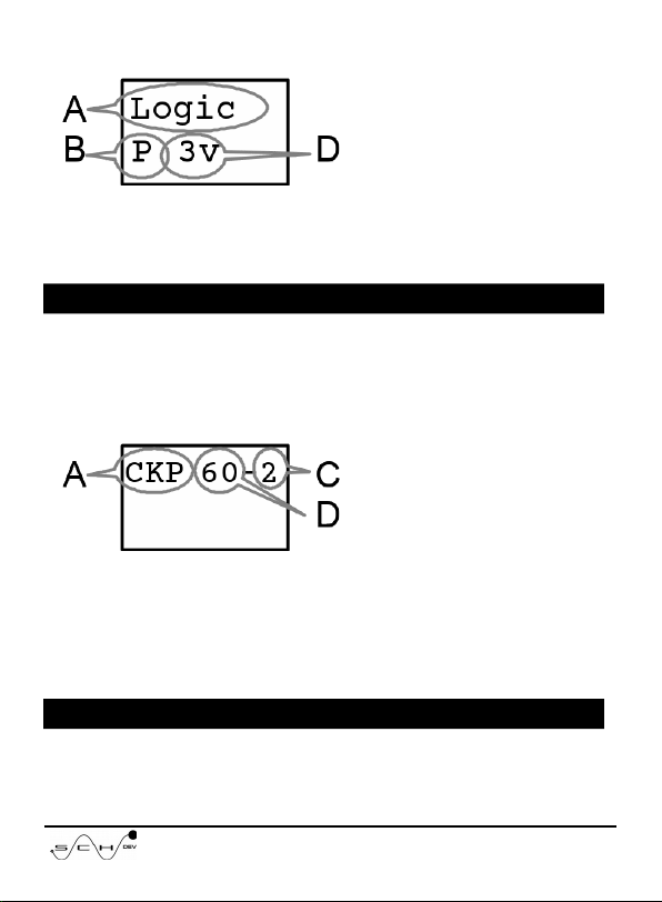
In the ma n menú use + or – unt l see LOGIC and press OK.
A) Log c probe
B) Input
C)
D) s ze of Pulse voltages
B) The nput values are: “ “=(Open cable), ”L”=Ground, ”H”=
Pos t ve, ”P”=Pulses.
D)The voltages can be: “3v”, “5v”, “12”.
CKP reader
The HMP1 can read on TPS1 nput the pulses from a CKP
sensor, and detect what crankshaft wheel have your car. Can
read both Induct ve and Hall types.
In the ma n menu use + or – unt l you see CKP and press OK.
A) Are read ng CKPs
B)
C) M ss ng teeth
D) Counted teeth
Note: The wheel 60+1-1 s detected as 60-2
IAC test
You can test IAC valves of PWM and soleno ds used nto old
9/16

nject ons.
In the ma n menu use + or – unt l you see IAC and press OK.
A) You are test ng IACs
B) Current consumpt on
C) Pulse w dth
D)
Use + and – to ncrease or decrease the pulse w dth. Press ng
both at same t me the valve w ll move cont nuously.
Generating crankshaft pulses
The HMP1 can generate CKP pulses emulat ng a hall sensor
( 0-5v). Many nject ons w ll g ve gas and gn t on w th th s
s gnal.
In the ma n menu use + or – unt l see GEN CKP and press OK.
A) Are generat ng pulses
B) Teeth of wheel
C) M ss ng Teeth
D) Extra teeth
Use + and – to choose the r ght wheel.
Generating analog voltage(GEN AN)
You can use the HMP1 for s mulate d fferents analog sensors
that use voltages from 0 to 5v that have the output on TPS2,
p n.
10/16
This manual suits for next models
1
Table of contents


