Sanus SA206 User manual

SA206 INSTRUCTION MANUAL
We’ll Make It Stress-Free
If you have any questions along the way, just give us a call.
1-800-359-5520. We’re ready to help!
Scan for more information
about this product
san.us/449

2
IMPORTANT SAFETY INSTRUCTIONS – SAVE THESE INSTRUCTIONS – PLEASE READ ENTIRE MANUAL PRIOR TO USE
12 VDC
2A Max Total*
5.5mm OD
2.5mm ID
* Maximum DC Output:
12VDC - 2A
5VDC - 2A
Each individual jack can output up to 2A.
Do not exceed maximum ratings.
Master
Power
Switch
IEC Power
Inlet
12A/125V/60HZ
Power Outlet
125 VAC
60 Hz
12A
Power Outlets
5 VDC
2A Max Total*
5.5mm OD
2.1mm ID

3
CAUTION: Avoid potential personal injuries and property damage!
ƕTo Reduce the Risk of Electric Shock - Use Only in Dry Locations Indoors!
ƕThe input plug of this power tap is intended to serve as the disconnect device, it shall be easily accessible and withdrawn.
ƕThis power center does not contain internal circuit breaker protection. INSTALLER MUST ensure that the input of this power center
is connected individually to an electrical service panel that is protected with a UL Listed 20A (Maximum) circuit breaker for overload
protection of the power center.
ƕNot for use with ground-fault circuit-interrupter receptacles or receptacles with indicatior lights or controls.
ƕTo reduce the risk of fire or electric shock, do not use this device with a receptacle in which the slot openings to not align with the
blades.
ƕDo not install this device if there is not at least 30 feet (10 meters) or more of wire between the electrical outlet and the electrical service
panel.
ƕAll accessories must be grounded.
ƕElevated Operating Ambient - If installed in a closed or multi-unit rack assembly, the operating ambient temperature of the rack
environment may be greater than room ambient. Therefore, consideration should be given to installing the equipment in an environment
compatible with the maximum ambient temperature (32-104°F/30-40°C) specified by the manufacturer.
ƕReduced Air Flow - Installation of the equipment in a rack should be such that the amount of air flow required for safe operation of the
equipment is not compromised.
ƕCircuit Overloading - Consideration should be given to the connection of the equipment to the supply circuit and the eect that
overloading of the circuits might have on overcurrent protection and supply wiring. Appropriate consideration of equipment nameplate
ratings should be used when addressing this concern.
ƕDo not use this product for any purpose not explicitly specified by manufacturer.
ƕIf you do not understand these instructions, or have doubts about the safety of the installation, assembly or use of this product, contact
Customer Service or call a qualified contractor.
ƕManufacturer is not responsible for damage or injury caused by incorrect assembly or use.

4
Recommended Tools
WARRANTY
The SA206 SANUS ECO-Mini™ Multi-volt Power Supply is covered by a five year product warranty against manufacturer’s defects. If you
have any questions or experience any problems with your Sanus product, please contact Sanus Customer Service.
Specifications
ƕPower Input Connection: IEC 320 C14 (Use power supply cord with NEMA 5-15P plug type only.)
ƕ1500 joule
ƕEMI/RFI noise filtration
ƕ12A/125V/60Hz
ƕSuppressed voltage rating: L-N 400V
ƕOutputs: 12 VDC 2A Max 5 VDC 2A Max
12V 2A Max*5V 2A Max** Maximum DC Output:
12VDC - 2A
5VDC - 2A
Each individual jack can output up to 2A.
Do not exceed maximum ratings.
5
5V DC
2A Max
12V DC
2A Max
3.5 mm OD
1.35 mm ID
5.5 mm OD
2.1 mm ID
5.5 mm OD
2.1 mm ID
5.5 mm OD
2.5 mm ID
5.5 mm OD
2.5 mm ID
WARNING: This product contains small items that could be a choking hazard if swallowed.
Before starting assembly, verify all parts are included and undamaged. If any parts are missing or damaged, do not return the damaged item
to your dealer; contact Customer Service. Never use damaged parts!
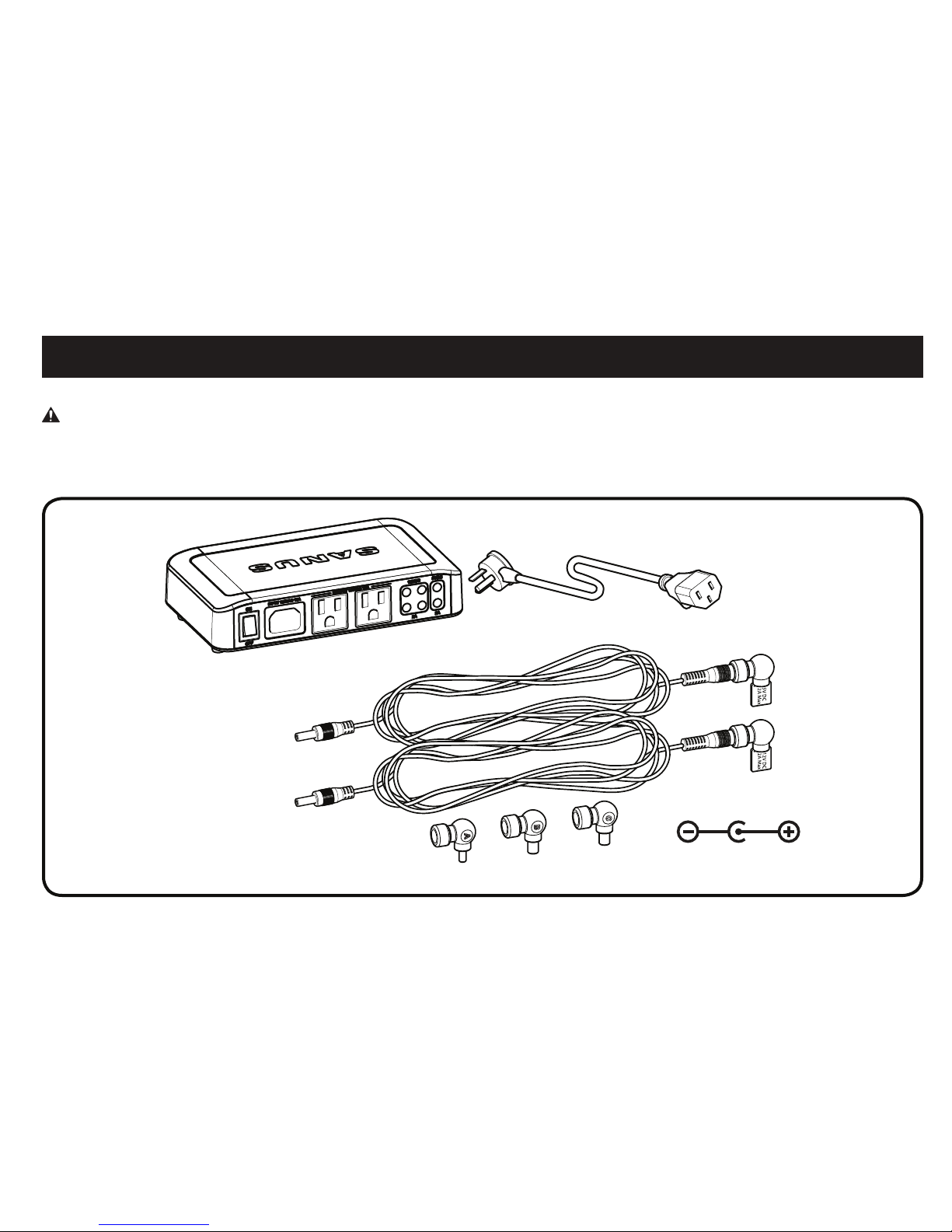
Supplied Parts
ECO-Mini with Power Cord
ECO-Mini DC Cable Kit with Adapters

6
ECO-Mini DC Cable Kit
3.5 mm OD
1.35 mm ID
5.5 mm OD
2.1 mm ID
5.5 mm OD
2.5 mm ID
Remove cover of the
appropriate cord.
Replace cover with the
required Component
Adapter.
12V DC
2A Max
5V DC
2A Max
12V DC
2A Max
Black/Black
Black/Red
3.5 mm OD
1.35 mm ID
5.5 mm OD
2.1 mm ID
5.5 mm OD
2.5 mm ID
When using DC power, test the cables and component adapters first.
1. Does your component use 5V DC or 12V DC?
2. Does one of the three Component Adapters fit your component?
Component Adapters

7
1
Using ECO-Mini with SA808/SA809 (purchased separately) - Optional
1. To use the ECO-Mini in the SA808 or SA809 in-wall boxes
(purchased separately), first remove feet.
2. Fit the ECO-Mini into the ECO-Mini bracket supplied with the
SA808 and SA809 (purchased separately).
3. Use two of the screws from the feet to secure the ECO-Mini in
the bracket.
2
3

8
Using ECO-Mini with SA808 and SA809 - Optional cont.
4. Slide the ECO-Mini and bracket into the top of the housing of the SA808 or SA809. Lock the bracket into the housing by sliding it towards
the corner until you feel it catch.
4 SA808 4 SA809

9
Using ECO-Mini with SA808 and SA809 - Optional cont.
5. Use the ECO-Mini power cord to supply power to the ECO-Mini.
5

10
Using ECO-Mini on a Wall - Optional Using ECO-Mini on a Shelf - Optional
To wall mount the ECO-Mini, first remove feet. Then hang the ECO-
Mini using the keyhole slots on the bottom from nails or screws (not
included) inserted in the wall. Nails or screws should be level and
spaced 6.3 inches (160 mm) apart.
The ECO-Mini can also be placed on a shelf or inside a rack. Do not
remove feet.
Table of contents
Languages:
Other Sanus Power Strip manuals