Rotech Sentinel MB24 User manual

t: +61 07 3205 1123 www.rotech.com.au e: [email protected]
Vehicle Access Control
Pedestrian Access Control
Safety & Security Equipment
Installation Instructions
Please read these instructions fully before installing
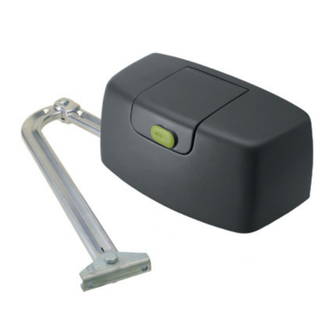
Sentinel MB24 Articulated Arm
Swing Gate Operator v02/23

AC
DE B
(1)With braking disabled
(2)See table
(3)Intensive use
(4)Permanent grease
(5)Customized key Door leaf max. rotation
Fig.1
Technical data MBE24 MB24V
Power supply
Motor feed
Power drawn
Current drawn
Torque
Noise level
Operating time at 90°
Door leaf max. weight
Door leaf max.
Jogging
Lubrication
IP class
Weight
Built-in release:
230 Vac
24 Vdc
160 W
0,76 A
180 Nm
<70 dB
10 s (1)
300 kg (2)
2,5 m(2)
(3)
(4)
IP44
10,7 kg
(5)
--
24 Vdc
160 W
6,2A
180 Nm
<70 dB
10 s (1)
300 kg (2)
2,5 m(2)
(3)
(4)
IP44
9 kg
(5)
Door leaf width
(m)
Door leaf weight
(kg)
1
1,5
2
2,3
300
250
215
200
350
350
184
245
95
234
28
35
α° A (mm) B (mm) C (mm) D (mm) E (mm)
90° 0 470 350 243 140
90° 50 470 339 255 140
90° 100 470 331 262 140
90° 150 470 328 264 140
90° 185 470 356 237 160
90° 200 440 410 160 200
110° 0 420 244 318 200
105° 100 420 262 310 200

Fig.2
57
27,5
140mm min.
Bracket
Articulated bracket

S
T
SN
D
R
N
B2
S1
B1
T1
P
A
Fig.3
Self locking nut M8 UNI 7473 Screw M8x65 UNI 5737 Fixing bracket
Fig.4

Fig.5
Customized key C
Lever L

GND
L
N
SWC2 (17) SWO2 (16) COM (13) M2 (3,4)
Fig.6
Cover
Cover
MBE24V
MB24V
Cables

Fig.7
Inside.
Open. Open.
Left Right
Open.
Close.
Lower cam
Upper cam Microswitch
Lower cam
Upper cam Key
Key
Open.
Close.
Upper cam
Lower cam
Key
Key
MB24
MBE24

3
1
7
2
3
5
6
4
3 x 1,5 min
Legend:
1 Ratio-motor MBE24V
2 Ratio-motor MB24V
3 Photo-electric cells FTC/FTM
4 Key selector CH
5 Mechanical stop
6 Blinker LAMP
7 Aerial AW
8 Articulated arm with brackets BA
RG 58
230V
2 x 1,5
4 x 0,35
2 x 0,35
2 x 0,35
3x0,5+
2x(2,5/4/6)
24V
2 x 0,35
2 x 0,35

14
Warning
• Before installation, carefully read the instructions hereunder.
• It is strictly forbidden to use the item MB24V/MBE24V for applications other than the intended uses de-
scribed in these instructions.
• Instruct the user on how to use the system.
Introduction
Thank you for choosing our MB24V/MBE24V ratiomotor. All items in the wide Benincà production range are
the result of twenty-years’ experience in the automatism sector and of continuous research for new materi-
als and advanced technologies. We are, therefore, in the position to offer higly reliable products that due to
their power, effectiveness and useful life, fully satisfy the final user’s requirements.
All our products are manufactured to the existing standard and are covered by warranty. Possible injury to
people or accidents caused by defects in construction are covered by a civil liability policy drawn up with
one of the major insurance companies.
1. General notes
For a good operation of the automatic system the door to be automated must feature the following charac-
teristics:
• Rugged and stiff door leaves.
• Efficient hinges.
• The door leaves should be moved by hand without any friction for the entire stroke.
• The doors should be complete with a catch in the closing phase.
In the negative, replace the faulty parts. Reliability and safety of the automatic system depend on the gate
structure.
2. Specifications
This automatic system is suited to motorise doors when overall dimensions, large pillars or columns impair
the use of traditional actuators. MB24V/MBE24V is equipped with an articulated arm BA which permits
smooth and noiseless movements, it is easy to assemble and, thanks to its pleasant design, is able to meet
the most stringent requirements. It is composed of an irreversible geared motor group, made with very strong
materials and two die-cast aluminium shells. The door opening is adjusted by limit switches. The system
can be released by an emergency lever with customized key which allows the manual operation of the gate
in the event of power failure.
3. Versions
MBE24V: 24Vdc , irreversible geared motor with built-in control unit
MB24V: 24Vdc , irreversible geared motor.
BA: Articulated arm with brackets.
4. Overall dimensions and limits for use (Fig.1)
For a correct installation check the limits for use and the overall dimensions, then calculate the values for
installation.
5. Anchoring of brackets (Fig.2)
Once the fixing value “E” it taken from the relevant table, and considering a minimum height from floor of
100mm, fit the bracket to the pillar by means of the screws M8 with relevant screw anchors.
Once the fixing value “B” is calculated, fit the articulated bracket to the gate with the same screws M8 and
relevant screw anchors or weld it to the gate by aligning the articulation bracket to the fitting bracket for the
pillar, as shown in the drawing. Reinforce the fitting areas which are not sufficiently thick, or in any case not
strong enough.
6. Positioning the geared motor (Fig.3)
Place the geared motor in the fitting bracket for assembly to pillar by using the special nuts and screws
supplied.

7. Positioning the articulated arm BA (Fig.4)
- Release the gear motor (see paragraph “Emergency manual operation”)
- Insert pin P in the hole of the motor shaft A
- Join arm B1 to arm B2 and lock them by means of pin T1 and lock ring S1
- Fix the arms to the motor shaft A and lock them by means of nut D by inserting washer R and ring N
- Hook the arm to bracket SN and lock it by means of pin T1 and release ring S1.
- Apply cover C and fix it by means of the two screws V.
The gear motor can be installed on the other gate leaf (Fig. 6) in a similar way. The only difference between
right-hand and left-hand leaves relies in the position of arm B2.
With released gear motor, completely open the gate and check the operating clearances of the two arms.
8. Manual and emergency operation (Fig.5)
To manually open or close the door in case of power failure or faults, two solutions are possible:
• Built-in release
Introduce the customized key C, turn it clockwise and pull lever L. At this point the geared motor is released
and the gate can be manually pushed.
To reset the normal operation, close lever L again and turn key C anticlockwise. Manually move the gate
until the geared motor is engaged again.
• Rope external release: optional
It is available for fitting to external wall or with accessory to be mounted flush (see MB.SE).
9. Wire connections (Fig.6)
For wire connections of the control unit, refer to instructions given in the control unit booklet.
Lay the cables, adequately placed in ducts, by tearing only the cover of the cable passage used.
Use a 3x0.5sqmm cable to connect the limit switches of MB motor to the control unit.
To connect the MB motor to the control unit, the cable cross section should comply with the values here-
under:
For cable length lower than 5m, use a cable 2x2.5sqmm
For cable length from 5 to 7.5m use a cable 2x4sqmm
For cable length from 7.5 to 10m use a cable 2x6sqmm
Cables longer than 10m are not recommended to connect control unit and motor.
If it is required to invert the rotation direction of the motor, invert the connections of motors in the control
unit, 1/2 for motor 1 (MBE24) and 3/4 for motor 2 (MB24).
10. Adjusting the limit switches (Fig.7)
N.B.: The position of the cams referring to micro-switches varies according whether the installation
of the geared motor is lefthand or righthand, view from inside. Pay attention to diagrams.
• Closing limit switches
Release the geared motor and manually close the door.
Turn the related cam to the position shown by using the special key supplied, until the micro-switch is
activated. Lock the cam by tightening the central screw supplied.
• Opening limit switches
Release the geared motor and manually open the door.
Turn the related cam to the position shown by using the special key supplied, until the micro-switch is
activated. Lock the cam by tightening the two screws supplied.
11. Adjusting the motor torque)
The torque adjustment is preset by the control unit. Please refer to the specific instructions.
An incorrect presetting of the torque may result in injuries or damages to property.
PLEASE COMPLY WITH REGULATIONS IN FORCE!.
CAUTION
The civil liability policy, which covers possible injuries to people or accidents caused by defects in construc-
tion, requires the system to be to existing standard and to use original Benincà accessories.
This manual suits for next models
1
Table of contents
Other Rotech Gate Opener manuals