
Rockford Fosgate AF/2HD User manual


TABLE
OF CONTENTS
Introduction
.........................................................................................................................................................
1
Input and Output Levels .....................................................................................................................................
2
Power Wiring Instructions ...................................................................................................................................
2
Fuse Protection ..................................................................................................................................................
2
Figure 1 Illustration View ...................................................................................................................................
2
Frequency Selection ...........................................................................................................................................
3
Band Selection ...................................................................................................................................................
3
Figure 2 Illustration View ....................................................................................................................................
5
Switching Examples ...........................................................................................................................................
6
Active vs. Passive Crossovers ...........................................................................................................................
6
Choosing Crossover Frequencies ......................................................................................................................
7
Specifications .....................................................................................................................................................
9
Warranty Information .......................................................................................................................................... 10
Make your
t*
%klbrdbxplcl
system complete
with
Installation accessones from
g*
hrktht&ce,
a division
of
Rockford
Corporation. Ask your sales
representative
about Perfect Power alternators, power cables, speaker
wire,
connectors, cosmetic accessories and fabric.
PRACTICE SAFE SOUND™
CONTINUOUS EXPOSURE TO SOUND PRESSURE LEVELS OVER 100dBMAY CAUSE PERMANENT
HEARING LOSS. HIGH-POWERED AUTOSOUND SYSTEMS MAY PRODUCE SOUND PRESSURE
LEVELS WELL OVER
130dB.
USE COMMON SENSE AND PRACTICE SAFE SOUND

Rockford
Fosgate
AF/2HD
is an active electronic crossoverthat incorporates HD (Hybrid Design)
to provide state-of-the-art flexibility, performance and pleasing aesthetics. Its features include: two
stereo inputs for true fading capability, infinitely adjustable frequency modules, user definable
high-
pass or low-pass filters, channel summing for mono applications, fully isolated high voltage power
supply, low noise circuitry, low distortion, high-load driving capacity 750 mV RMS input level, 750 mV
RMS output level.
.
.
.
.
.
.
.
.
.
.
.
.
.
FADING CAPABILITY
The
AF/2HD
can be configured for fading and non-fading installations.
LEFT AND RIGHT CHANNELS CAN BE SUMMED FOR MONO APPLICATIONS
Left and right channels can be summed to obtain one summed output for mono applications.
USER SELECTABLE FILTERS (HIGH PASS OR LOW PASS)
A wide range of hybrid modules allows the designer to select high or low pass filter to fulfill
sonic pleasures.
GOLD PLATED RCA’S
This provides the most accurate signal transmission and the lowest possible loss. Gold plated
terminals are immune to signal deterioration with time that can be caused by corrosion in
the connectors.
INTERNAL FUSE FOR PROTECTION
The
AF/2HD
has a built-in
1/2
amp fuse for protection from excessive current drives.
CONCEALED MOUNTING
The
AF/2HD’s
concise cabinet gives the installer the option of concealing the unit anywhere in
the automobile without worrying about heat dissipation.
AUDIO CIRCUIT IS HYBRID DESIGNED
The new
AF/2HD
incorporates hybrid circuitry which carries different surface-mount compo-
nents that are laser trimmed to exacting tolerance.
LOW DISTORTION
Such hybridization leaves more area on the “mother” circuit board for traces which provide
zero signal loss and reduces crosstalk and distortion.
WIDE RANGE OF FREQUENCY MODULES, OR FASHION YOUR OWN
Rockford
Fosgate provides the information about the operating range of their drives so that
you can choose a crossover frequency within that range to obtain maximum performance.
SMALL, LOW COST
The miniature hybrid chips eliminate space on the PC board and help reduce the cost which is
passed on to the customer.
HIGH LOAD DRIVING CAPACITY: CAPABLE OF HANDLING UP TO 10
ROCKFORD
FOSGATE AMPLIFIERS
The
AF/2HD
active crossover uses 2 hybrid modules for active gain stages which makes it
capable of handling up to 10
Rockford
Fosgate amplifiers.
12dB/OCTAVE
CROSSOVER SLOPES
Single component passive crossovers provide 6dB per octave
rolloff.
But the
AF/2HD
inte-
grates complex active circuitry to achieve a 12dB per octave
rolloff.
CASCADING OF OUTPUT TO INPUT PROVIDES 24dB/OCTAVE SLOPE
OR 12dB PER OCTAVE
BANDPASS
FILTER
1
.
INTRODUCTION
The

INPUT AND OUTPUT LEVELS
The AF/2HD is designed for preamp-level (750
mVRMS)
levels. Speaker-level inputs must be
attenuated to under 1.O VRMS.
/
Net gain in the filter
passband
of the
AF/2HD
is unity. (Output levels are equal to input levels)
POWER WIRING INSTRUCTIONS
1
The Black 16-gauge wire should be grounded to the chassis. The White
16-gauge
wire should be
connected to a source of constant +12-Volt power. The Red
16-gauge
wire is the trigger or turn-on
wire. Connect it to the source unit’s “Accessory” or “Auto-Antenna” lead, or to some other point that
has 12V “positive” when the system turns on. See Figure 1.
PROTECTION FUSE
The AFMHD has a built-in main power fuse for over current protection. If blown, replace with
AGC
1/2
amp fast blow fuse. See Figure
1
for fuse location.
AF/2HD WIRING/FUSE/MODULE AND JUMPER LOCATIONS
Switches For Number
Of Inputs And A
Summing Channel
I
Modules For Band
And Frequency\Situation
Inputs
-
outputs
Circuit Hybrids
Fuse
½
Amp
Fast Blow
_
Power Led
Ground Auto Power
Mounting Holes
&
Locations
FIGURE
1
2

FREQUENCY SELECTION
Custom crossover frequency modules will allow you to create notch filters or overlap frequencies to
“equalize” in or out a desired response.
High and Low crossover frequencies in the AFMHD are selected by inserting frequency modules in
sockets in the internal PC board.
In order to change a frequency module, remove the four machine screws that hold the cover and
remove the cover. Remove the frequency module you wish to change, and insert the new module in
its place.
See Fig.
1
for module locations.
AF/2HD
can be defined as either high or low pass fiters allowing the following
combinations:
hh
CHANNEL A:
HIGHPASS
CHANNEL B:
LOWPASS
GAIN
(dB)
GAIN
(dB)
20Hz
X
>>
20kHz 20Hz
Y
20kHz
FREQ. (Hz) FREQ.
(Hz)
CHANNEL A: HIGHPASS
CHANNEL B: HIGHPASS
GAIN
(dB)
GAIN
(dB)
20Hz
X
20kHz
FREQ.
(Hz)
hCHANNEL A: LOWPASS
GAIN
(dB)
20Hz
Y
20kHz
FREQ.
(Hz)
ACHANNEL B: LOWPASS
GAIN
(dB)
3
>
20Hz X20kHz 20Hz
Y
20kHz
FREQ. (Hz) FREQ.
(Hz)
NOTE: X AND Y ARE VARIABLES. THEY DEPEND ON THE MODULES USED ON THE BOARD.
3
7
WARNING! TURN OFF SYSTEM BEFORE REMOVING MODULES!
BAND SELECTION
I
Both channels in the
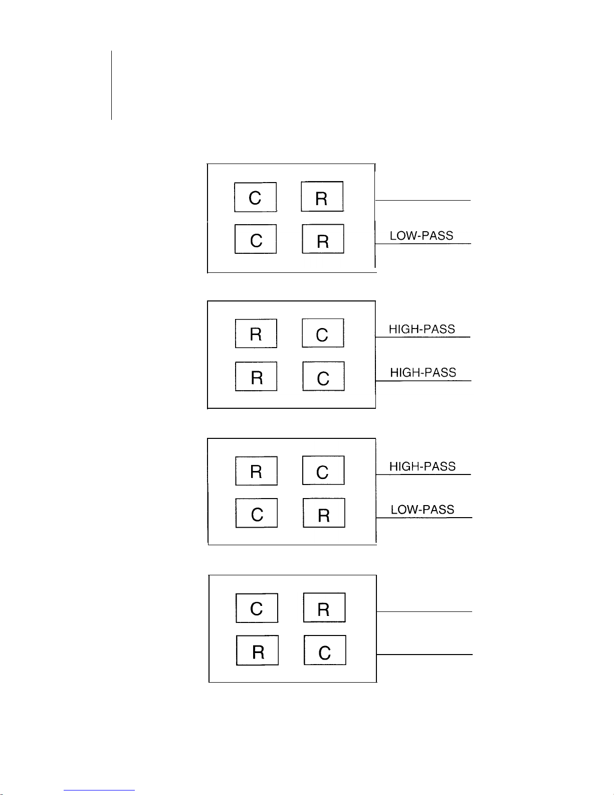
The selection is done simply by placing the capacitor module (C) in the socket location marked High
or Low on the PC board (See Figure 2). The empty location is where the resistor frequency module
(R) is placed. See the pictures in band and frequency section.
Note: Each channel can do both types of filters depending on where you put the capacitor
module.
/cI
LOW-PASS
m
LOW-PASS
El
ICI
HIGH-PASS
4

Low Pass Location
Crossover Module
_
Capacitor Module
AF/2HD
BAND & FREQUENCY
MODULE LOCATIONS
Capacitor Module
High Pass Location
FIGURE 2
5


.
FREQUENCY CONTROL: With an active crossover, frequency control is not dependent on
the impedance of the speaker.
.
CROSSOVER SLOPE: In an active
12dB
per octave crossover, slope is incorporated along with
the ability to make it 24dB per octave.
.
FREQUENCY SELECTION: With an active crossover, frequency selection is infinite.
CHOOSING CROSSOVER FREQUENCIES
Choosing the correct crossover frequency can be difficult. Consideration of the following items will
help you make your selection easier.
OPERATING RANGE OF SELECTED DRIVERS:
Manufacturers will usually provide information about the operating range of their drivers so that you
can choose a crossover frequency within that range to obtain maximum performance.
DESIRED POWER HANDLING OF DRIVERS:
High-pass crossovers can be changed to increase the power handling of a given driver. For example,
a tweeter may handle 50 watts at 10 kHz, but only 2.5 watts at 4 kHz.
DESIRED RESPONSE OF SYSTEM:
Most autosound installations introduce a number of acoustical problems that can sometimes be
corrected with careful attention to your crossover frequencies. The use of
1/3
octave RTA can help
you determine if a problem exists and at what frequency.
The following crossover frequencies work the best with
Rockford
Fosgate drivers, and provide a good
foundation for any autosound system.
Woofer 100 Hz Low-pass
Midbass 100 Hz High-pass-275 Hz Low-pass
Midrange 275 Hz High-pass-8 kHz Low-pass
Tweeter 8
kHz
High-pass
NOTE: Depending on the desired response of a given system, crossover frequencies can be
varied accordingly.
7

Table of contents
Other Rockford Fosgate Crossover manuals

Rockford Fosgate
Rockford Fosgate AudioPhile LP-1 User manual

Rockford Fosgate
Rockford Fosgate Punch 2X User manual

Rockford Fosgate
Rockford Fosgate AF/4HD User manual

Rockford Fosgate
Rockford Fosgate SYMMETRY EPX2 User manual

Rockford Fosgate
Rockford Fosgate Punch Audiophile ND4-XFM User manual

Rockford Fosgate
Rockford Fosgate Punch 3X User manual

Rockford Fosgate
Rockford Fosgate XOM Owner's manual

Rockford Fosgate
Rockford Fosgate Punch PP4-X User manual

Rockford Fosgate
Rockford Fosgate PunchX User manual


