Ringdale Token Ring - Ethernet TCP/IP Router User manual

Connecting people and information
RINGDALE
TT
TT
Tokok
okok
oken Ring - Etherneten Ring - Ethernet
en Ring - Etherneten Ring - Ethernet
en Ring - Ethernet
TCP/IP RTCP/IP R
TCP/IP RTCP/IP R
TCP/IP Routerouter
outerouter
outer
Connects a Single TConnects a Single T
Connects a Single TConnects a Single T
Connects a Single Tokok
okok
oken Ring Deviceen Ring Device
en Ring Deviceen Ring Device
en Ring Device
to an Ethernet Networkto an Ethernet Network
to an Ethernet Networkto an Ethernet Network
to an Ethernet Network
User ManualUser Manual
User ManualUser Manual
User Manual

Version 1.2 February 2002
COPYRIGHT
Copyright 2002 © Ringdale UK Ltd. All rights reserved. No part of this
publication may be reproduced, transmitted, transcribed, stored in a
retrieval system, or translated into any language or any computer
language, in any form or by any third party, without prior
permission of Ringdale UK Limited.
DISCLAIMER
Ringdale UK Ltd. reserves the right to revise this publication and to make
changes from time to time to the contents hereof without obligation to notify
any person or organisation of such revision or changes. Ringdale UK Ltd.
has endeavoured to ensure that the information in this publication is
correct, but will not accept liability for any error or omission.
TRADEMARKS
All trademarks are hereby acknowledged.
Part No. 62-13280005

Contents
Introduction 4
Typical Set-Up for the
Token Ring - Ethernet Router 5
Installation 6
Using PeripheralVision®to
Configure the Router 9
IP Router Page 10
Passwords 11
Routing Table Page 11
Broadcast Forward Page 12
PeripheralVision®Licensing 13
Token Ring Speed Settings 14
Upgrading Firmware 15
Safety and Location Advice 16
Technical Specification 17
Troubleshooting Guide 18
3

4
Introduction
Ringdale’s Token Ring - Ethernet TCP/IP Router provides a
solution for connecting a single Token Ring device (through a
MediaAccessUnit)toanEthernetnetwork. Thisallowsadevice
with a Token Ring network connection (for example Printers,
Laptops and network peripherals) to be attached to an Ethernet
network.
Ethernet connection is made with an RJ-45 connector,
configured to allow a crossover cable to run to the 10baseT
Ethernet Network.
Token Ring connection is made using a type 1 cable on a 9-
way DB connector or type 3 cable on an RJ-45 connector. The
router has the ability to automatically sense which Token Ring
connection is used and the Token Ring speed, at either 4MHz
or16MHz.
The router is configured and managed remotely using
Ringdale’s PeripheralVision®network management software
that can be installed on any Windows 95/98/ME/NT4/2000 PC
on the Token Ring network.
Follow the steps detailed in this manual for quick installation
of the Token Ring - Ethernet TCP/IP Router.
5
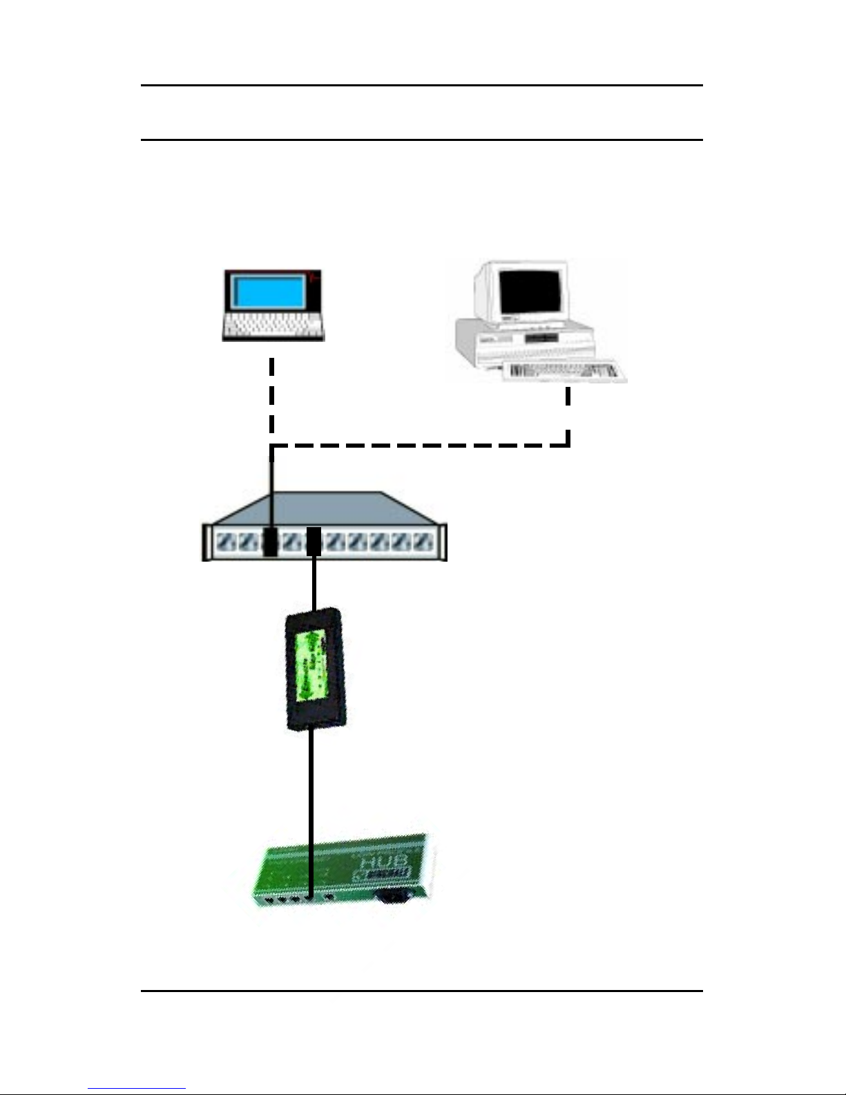
Laptop or PC with Token Ring Network Interface
Ringdale Token Ring to
Ethernet Router
Token Ring MAU
(Media Access Unit)
Typical Set-Up for Token Ring - Ethernet Router
Ethernet Hub
or Network Connection
Note:
Crossover Cable
Required Here
6
Installation
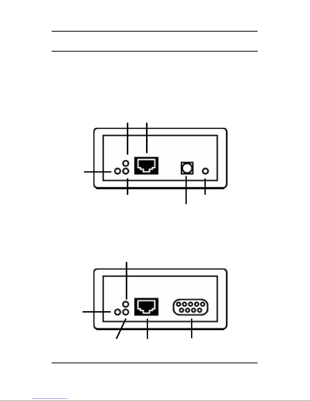
Connectors and LEDs
Ethernet Panel
Token Ring Panel
Token Ring (Type 3)
RJ45 Conn
Token Ring (Type 1) DB 9 Conn
Red Transmit LED
Green
Receive LED
Red
Error
LED
RJ45 Conn
Red Power LEDGreen Receive LED
Power Supply Conn
Yellow
Activity
LED
Red Transmit LED

7
Connecting the Router to the Ethernet Network
Insert a Crossover RJ-45 10baseT cable from the Ethernet
network into the RJ-45 port on the Ethernet panel.
The Green RX LED will blink when the router receives data
from the Ethernet network.
The Red TX LED will blink when the router transmits data to the
Ethernet network.
The Yellow Link LED indicates that the Ethernet network
connection is functioning.
Connecting the Router to the Token Ring Device
Connect the Token Ring device to the MAU (the type of cable
required will depend on the type of connections being used).
Insert
either
a Type 3 cable with a RJ-45 connector
or
a Type 1
cable with a 9 way DB connector from the Token Ring MAU into
theRJ-45
or
DB 9 porton the Token Ring panel. The routerwill
autosense
which Token Ring connector is being used.
The Red Error LED will light when there is an error with the
Token Ring devices.
The Green RX LED will blink when the router receives data
from the Token Ring device.
The Red TX LED will blink when the router transmits data to the
Token Ring device.
Powering the Router
Important Note
If there is a delay in connecting the router to the Token Ring
MAU after power-up, it may be necessary to restart the router in
order to make the Token Ring link good.

8
Connect the power cable to the Power Supply socket on the
Ethernet panel of the router. Connect the other end of the
power cable to the mains electricity supply.
Configuring the Router
Once the router is installed it is necessary to configure the
device. Configuration is accomplished by using the
PeripheralVision®software supplied with the router (see the
following chapter for details on this).
9
Using PeripheralVision®to Configure the Router
Full operational procedures for PeripheralVision
®
are detailed
in the program helpfile, refer to this if any problems are
encountered in the procedure detailed below.
1 Install PeripheralVision®onto a PC on the Ethernet network.
2 Ensure the router hardware installation is complete.
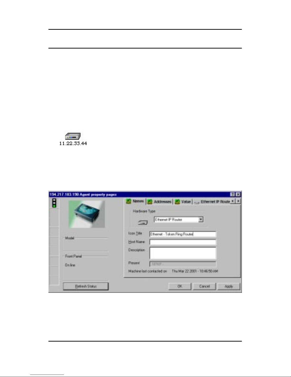
3 Using the Locate NPMPTM discovery tool in
PeripheralVision®, enter the default set IP
address (11.22.33.44). The router will appear
on the network map, it will be an icon similar to
the example on the left.
4 Left click twice on the icon to open up the property pages of the
device. The default displayed page will be the Name page.
This is shown below:
5 In the Icon Title field enter a name for the router that will allow it
to be identified on the PeripheralVision®network map.
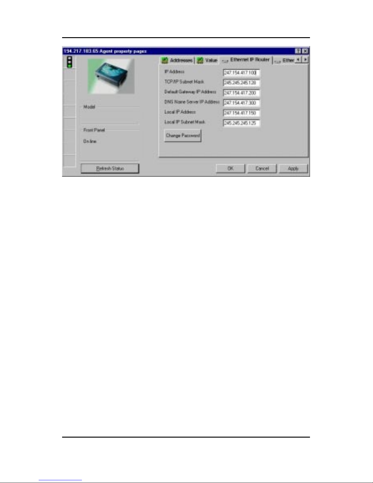
6 Using the arrows in the top right corner, scroll the pages and
click on the first IP Router page. This is shown following:
10
The following information needs to be entered onto this page
(this will be supplied by your network administrator).
IP Address Enter here the router’s IP address for the
Ethernet network (this will be the gateway for all
Ethernet devices that need to communicate with
the Token Ring device).
TCP/IP Subnet Mask Enter here the subnet mask for the Ethernet
network.
Default Gateway IP Address Enter here the IP address of another router.
This will allow packets for unrecognized IP
addresses to be redirected to that router.
DNS Name Server Address Enter here the IP Address of the DNS server
if required (optional).
Local IP Address Enter here the router’s IP address for the Token
Ring side (this will be the gateway for the Token
Ring device).
Local IP Subnet Mask Enter here the subnet mask for the Token Ring
side.
Click on Apply to register the new information.
This manual suits for next models
1
Table of contents
Other Ringdale Network Router manuals


