
RGBlink M3 User manual

M3 Quick Start
Integrated Vision Mixer
Full preview to program presentation switching
Additional background layer capability
Dual angle adjustable LCD monitors
Multi-View input sources
Full modular design
Combination module for greater flexibility
Configurable Genlock built-in
Tally support built-in
Support subtitles import and preview
Support scene edit and seamless switching
Save configurations on board and to USB
Optional Redundant Hot Swap PSU

© Xiamen RGBlink Science & Technology Co., Ltd.
1
1 / 41
CONTENT
Product Introduction...................................................................................................................................................2
Packing Configuration................................................................................................................................................. 3
Hardware Orientation................................................................................................................................................. 4
Front Panel.......................................................................................................................................................... 4
Back Panel........................................................................................................................................................... 9
Using Your Product.................................................................................................................................................... 11
Content.............................................................................................................................................................. 11
Menu Structure......................................................................................................................................... 12
PVW Mode................................................................................................................................................ 13
PST Mode.................................................................................................................................................. 14
PGM Mode................................................................................................................................................ 21
AUX Mode............................................................................................................................................... 22
4K1K Mode..............................................................................................................................................31
Switching Mode.........................................................................................................................................33
Set the Output Resolution........................................................................................................................ 34
Using Black Out......................................................................................................................................... 37
Saving Views..............................................................................................................................................38
Recall Saved Settings.................................................................................................................................39
Contact Information.................................................................................................................................................. 40

© Xiamen RGBlink Science & Technology Co., Ltd.
2
2 / 41
Product Introduction
M3 brings together sophisticated presentation switching with advanced mixing capabilities into a single device.
The vision mixer console includes broadcast style features for quick access during any performance, along with
dual eight-inch LCD displays to monitor video sources, full preview, as well as live/program display monitoring.
At the rear of the M3, the familiar VENUS X3 modular routing platform become apparent, with a host of new
options and features tailored to presentation applications.
Entirely module, right down to fans, filters, and PSU, M3 is fitted as standard with modules for preview and
monitoring, communications and Genlock sync. From there, there is an impressive choice of both inputs and
output options.
The on board displays can be configured to show outputs as physically arranged, or in any way. Large tactical
illuminated buttons along with T-Bar mixing control. Powerful, yet compact, M3 is a fully integrated scaling,
processing and mixing for processing and mixing for professional environments from entertainment to
integration.
System Connection
RGBlink offers solutions to demanding
technical problems. Any application
questions, or required further
information, please contact with our
customer Support Engineers.
M3 System Connection Diagram

© Xiamen RGBlink Science & Technology Co., Ltd.
3
3 / 41
Packing Configuration
Note:
SDI cable supplied only when SDI Output module is factory fitted
AC Power Cable supplied as standard according to destination market.
AC Power Cord
USB Cable
DVI-I to RCA
Convertor
Network Cable
SDI Cable
DVI Cable
Screw Driver
HDMI to DVI
Cable
Antistatic Bag

© Xiamen RGBlink Science & Technology Co., Ltd.
4
4 / 41
Hardware Orientation
Front Panel
Panel Instruction
1
LCD display
10
AUX button
2
Multiview presets area
11
Menu area
3
Layer/Aux area
12
Stored presets area
4
Power button
13
Lock top panel area
5
Position, Size and Control area
14
Transition time control area
6
DSK edit area
15
WIPE operation area
7
BLEND edit area
16
OSD edit area
8
Input sources area
17
Switch Modes area
9
Black button

© Xiamen RGBlink Science & Technology Co., Ltd.
5
5 / 41
Power Button
4
POWER: When yellow light is lit, the device is standby, while when green light is lit, the
device is starting up.
LCD Display
1
LCD Display
8 inch full-color display.
PVW Monitor (left): Multiview preview.
PVW: Eight images and single image preview switching button.
CHNL: Custom the eight channels.
Rotary: For PVW menu selections, adjustment and confirmation.
PST/PGM Monitor (right): Preview edit.
PGM: For PST and PGM switching.
LOGO: Custom the logo.
OSD: Custom the OSD.
STILL: Custom the STILL.
AUX: Quick split for PGM/SPGM output card.
FMT: Output format setting button.
Rotary Knob: For PST menu selections, adjustment and confirmation.
Layer/Aux Button
3
Button 1/2/3/4: For adding or deleting the layer.
FREEZE: Freeze the image or video.
Multiview Presets Area
2
Multiview Presets
: 1P
: PIP CENT
: SIDE BY SIDE
: 3P
: 4P

© Xiamen RGBlink Science & Technology Co., Ltd.
6
6 / 41
: 5P
Position, Size and Control Area
5
CONTROL: Layer selection button.
SIZE: Size adjustment and crop setting.
POSTION Joystick: Position adjustment button.
DSK Edit Area
6
DSK: DSK effect editing button
ON: ON/OFF button
LEVEL Rotary Knob: Adjust the alpha of DSK layer.
BLEND Edit Area
7
BLEND: BLEND effect editing button
ON: ON/OFF button
LEVEL Rotary Knob: Adjust the blend width.
Input Sources Area
8
LED Indicator: The button 1/2/3/4/5/6/7/8 is lit when the signal or background input is
selected for use.
PGM area
BK: Indicating function, the button is lit when enable background function.
OSD: Indicating function, the button is lit when enable OSD function.
LOGO: Indicating function, the button is lit when enable LOGO function.
STILL: Indicating function, the button is lit when enable STILL function.
1/2/3/4/5/6/7/8: Each button is numbered and can be used as direct number entry
when values such as resolution and size.
PST/Aux area
BK: Editing function, the button is lit when enable background function.
OSD: Editing function, the button is lit when enable OSD function.
LOGO: Editing function, the button is lit when enable LOGO function.
STILL: Editing function, the button is lit when enable STILL function.
BLACK Button

© Xiamen RGBlink Science & Technology Co., Ltd.
7
7 / 41
9
BLACK: The button is lit when enable black function.
SPGM Button
10
SPGM: SPGM output setting, it can be custom.
Menu Area
11
SYSTEM: Menu and exit reuse button.
ENTER: Confirmation button.
Menu Rotary Knob: Menu selection and confirmation button.
Stored Presets Area
12
SAVE: Support 36 saving modes.
LOAD: Load saving views 1 to 36.
PAGE: For save or load, total 6 pages, and 6 banks for each page.
1/2/3/4/5/6 Button: The button is lit when select PAGE or BANK.
Lock Top Panel Area
13
LOCK: Lock top panel button.
Transition Time Control Area
14
Double Digital Display Tube: Display the transition time.
Time Rotary Knob: Adjust transition time.
WIPE Operation Area
15
: ←□→, →□←, ←+→, →+←, L←M→R, T←M→B
: ←O→
: R→L, L→R
: T→B, B→T, LT→RB

© Xiamen RGBlink Science & Technology Co., Ltd.
8
8 / 41
: III→
: FADE
OSD Edit Area
16
: Subtitle rows back button.
: Subtitle rows forward button.
OSD TAKE: Subtitles switch button.
Switch Mode Area
17
CUT: Seamless switching.
TAKE: Seamless switching with effect.
T-BAR: WIPE and fade switching.
© Xiamen RGBlink Science & Technology Co., Ltd.
9
9 / 41
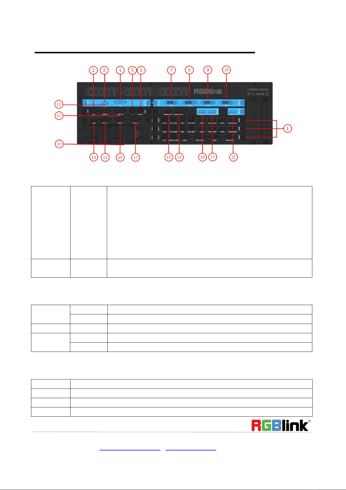
Back Panel
Input Interface
Option Input
Module
1
3 input card slots, supports input signals including DVI, VGA, HDMI, USB, CVBS
and USB.
Each DVI module supports 4 DVI-I inputs.
Each VGA module supports 4 DB15 inputs.
Each HDMI module supports 4 HDMI-A inputs.
Each USB module supports 4 USB-A inputs.
Each CVBS module supports 8 BNC inputs.
Each SDI module supports 4 SDI inputs and 4 SDI loop out.
Background
input
18. 19
HDMI input HDMI-A port
Output Interface
PGM Output
7. 8. 9. 10
DVI output DV-I port
20. 21
HDMI output HDMI-A port
PST Output
22
HDMI output HDMI-A port
PVW
Output
3
HDMI output HDMI-A port
4
VGA output DB15 port
Control Interface
2
LAN port RJ-45
14
USB interface USB-A port
11. 12
RS-232 Interface
5. 6
5: Genlock input BNC port
Other manuals for M3
1
Table of contents
Other RGBlink Recording Equipment manuals



