resi-linx HD-4001 digi-mod Instruction Manual

HD-4001DM User Guide and Install Manual Page 1
HD-4001 Quad Input DVB-T HD Encoder/Modulator
User Guide and Install Manual
Table of Contents
Safety Precautions..........................................................................................................................................2
Package Contents ...........................................................................................................................................2
Product Description........................................................................................................................................3
Specification...................................................................................................................................................4
Installation......................................................................................................................................................5
Hardware Installations and Connections........................................................................................................5
Connecting to the GUI Interface:...................................................................................................................6
Encoder Programming and Setup via GUI Interface: ....................................................................................6
Overview Page of Zycast Encoder.................................................................................................................6
Common Setup...........................................................................................................................................7
RF Setup....................................................................................................................................................9
Encoder Setup ............................................................................................................................................9
Network Configuration ...........................................................................................................................11
Administration............................................................................................................................................12
Saving your configuration files....................................................................................................................12
Front Panel LCD Encoder Menu Map .........................................................................................................13
Modulator Configuration via Front Panel LCD...........................................................................................14
Network Setup............................................................................................................................................18
ASI Output .................................................................................................................................................18
EAS ...........................................................................................................................................................19

HD-4001DM User Guide and Install Manual Page 2
Safety Precautions
The presence of this symbol is to alert the installer and user to the presence of uninsulated dangerous
voltages within the product’s enclosure that may be of sufficient magnitude to produce a risk of electric
shock.
TO REDUCE THE RISK OF FIRE OR ELECTRIC SHOCK, DO NOT EXPOSE THIS DEVICE
TO RAIN OR MOISTURE. DO NOT OPEN THE UNIT. REFER SERVICING TO QUALIFIED
PERSONNEL ONLY.
DO NOT apply power to the unit until all connections have been made, all components have been
installed and all wiring has been properly terminated.
DO NOT terminate, change or uninstall any wiring without first disconnecting the unit’s power adapter
from the device.
This device is supplied with the appropriately rated power supply. The use of any other power supply
could cause damage and invalidate the manufacturer’s warranty.
DO NOT connect the power cord to the device if the power cord is damaged.
DO NOT cut the power cord.
DO NOT plug the power cord into an AC outlet until all cables and connections to the device have
been properly connected.
The device should be installed in an environment consistent with its operating temperature
specifications. Placement next to heating devices and ducts is to be avoided as doing so may cause
damage. The device should not be placed in areas of high humidity.
DO NOT cover any of the device’s ventilation openings.
DO NOT cover or obstruct the device’s fan or fan openings.
If the device has been in a cold environment allow it to warm to room temperature for at least 2 hours
before connecting to an AC outlet.
Package Contents
This package contains:
One HD-4001DM Encoder / Modulator*
One power cable
One installation / configuration manual
Inspect the package before starting installation to ensure there is no damage and all supplied contents are
present. Contact your distributor or dealer should the device be damaged or package contents are
incomplete.

HD-4001DM User Guide and Install Manual Page 3
Product Description
resi-linx digi-MOD HD Series Encoder/Modulators provides a DVB-T & ASI output stream - making it
ideal for any Commercial RF Network. The high quality HD design allows for watching action packed
movies and sports channels on any HDTV. The optional AC-3 Dolby Audio, EAS, and AES-128
Encryption capabilities rounds out the feature rich product series. The space saving design delivers up to
4 High Quality HD DVB-T channels in a single 1RU space.
Front panel LCD Display for easy installation
High Resolution 1080i/1080p
LCN MODE
Composite, Component, and HDMI (unencrypted) inputs
MPEG2 or MPEG4(AVC) Video Output
Selectable Constellation
Closed Captioning Support
100dB Output
Newly Added EAS Functionality*
Rack mountable 1RU height
Front Panel
Rear Panel

HD-4001DM User Guide and Install Manual Page 4
Specification
VIDEO INPUTS (Video by Priority)
HDMI
1.4v
Component
YprPb (RCA)
Composite
CVBS (RCA)
AUDIO INPUTS
Audio Inputs
L/R (RCA)
Video Encoder
Mode
MPEG-2, MPEG-4(AVC)
Video Resolutions
1080p (AVC Only), 1080i, 720p, 576p, 576i, 480p, 480i
AUDIO Encoder
Audio Compression
MPEG-1 Layer II, AAC, AC-3 (Optional), AC-3 Pass Through
RF DVB-T Support
Frequency
Channel Plan - Varies by Country
RF Channel Output
4 multiplexed on to 2 RF Output
Constellation
64QAM (16QAM)
Bandwidth
7 MHz
RF Level Output
100dB
MER
>40dB Typical
FEC
1/2, 2/3, 3/4, 5/6, 7/8
Guard Interval
1/4, 1/8, 1/16, 1/32
OFDM
8K (2K)
Attenuation
1-20dB (1dB steps)
RF Output
"F" - Female 75 ohm
Closed Captioning Control
By Selection (use of CVBS Input)
EAS Support
Connection
Terminal Type
Video Input
CVBS (RCA)
Audio Input
L/R (RCA)
ASI Support
Connection
75 ohm (BNC)
Output
TS Multiplexed
IP Output - not available
Management / Control
Front Panel LCD Control
Full Support (Up/Doen/OK Buttons)
GUI
IE9, Firefox, Chrome, Safari
Password Protected
Front Panel, GUI
General
Rack Mountable (1RU)
482.7mm x 240mm x 44.4mm - 19" EIA Standard
Internal Fan Cooled
Dual Internal
LCD Front Panel
Dual Line, Scrolling Display
**Subject to change without noticifications

HD-4001DM User Guide and Install Manual Page 5
Installation
System Installer must adhere to Article 820-40 of the NEC that provides guidelines for proper
grounding and specifies that the cable ground shall be connected to the grounding system of the
building, as close to the point of cable entry as possible.
Unpacking and Inspection
Each unit is shipped factory tested. Ensure all items are removed from the container prior to discarding
any packing material.
Thoroughly inspect the unit for shipping damage with particular attention to connectors and controls. If
there is any sign of damage to the unit or damaged or loose connectors contact your distributor
immediately. Do not put the equipment into service if there is any indication of defect or damage.
Hardware Installations and Connections
It is highly recommended that quality cables and connectors be used for all video and audio source
connections.
1. The unit is designed to be rack mounted in a standard EIA 19” rack.
2. The unit comes standard with HDMI, Component, and Composite video inputs. The HDT encoder
/ modulator are intelligently designed to detect the video input from the video source. HDMI
Connection: Connect the HDMI cable(s) from the video source(s) into the HDMI input(s). If
using a Component Video Cable, connect the Y (Green), Pb (Blue), and Pr (Red) video source
cable to the unit’s Component input ports. If using a Composite Video source, use a 75Ω coaxial
cable with RCA connectors to connect the video source (e.g., CATV, DVD, VCR, Camera) to the
unit’s CVBS port (IN1…IN2, IN3, IN4 depending on your model).
Repeat this step for each video source connection.
3. Component / Composite Audio inputs: Connect A/V audio input (Left / Right Audio) use RCA
cables to connect the audio source to the red / white AUDIO L and AUDIO R INPUT jacks
(IN1…IN2, IN3, IN4 depending on your model). Repeat this step for each audio source
connection.
Be sure the video and audio connections for each source are consistent with the unit’s inputs
(IN1…IN2, IN3, IN4 depending on your model).
4. Use a quality 75Ω coaxial cable with “F” connectors from the unit’s RF OUT jack to the
distribution system (combiner or reverse splitter) or directly to a television.
5. If your device is equipped with an IP output- connect the Ethernet cable to the IP output RJ45
connector.
6. If your device is equipped with an ASI output- connect the BNC cable to the ASI output.
7. If your device is EAS equipped make the proper connections (contact replay and Video /Audio
Inputs) to the EAS device.
8. Connect the included power cord to the unit’s POWER plug.
9. Connect the power cord to an appropriately rated AC power outlet.

HD-4001DM User Guide and Install Manual Page 6
DEVICE Programming and Setup
To setup and program the Encoder you can use the GUI interface or
the LCD Front Panel
Connecting to the GUI Interface:
1.Connect an Ethernet cable directly (no Cross Over cable required) to the Web Management Port
on the rear panel of the encoder or connect the Ethernet cable to an Ethernet switch. Connect an
Ethernet Cable to your PC.
2.Using a Windows-based PC Select Windows Icon
3.Go to My Computer
4.Select Network
5.Allow UPnP to locate and list the device(s) in the right panel
6.Right Click and Select “View device Webpage”.
Note: For Setup Using Front Panel LCD:
Go to Page 15 in this manual.
Encoder Programming and Setup via GUI Interface:
After connecting the device to the “Web Management” port located on the rear of the device and locating
the device via the 'Network' tool in 'My Computer'
Step 1: Right Click and Select “View device Webpage”.
Overview Page of resi-linx digi-MOD HD
Overview status of the Encoder when fully functioning.
Alternate between viewing status of RF Output 1 and RF Output 2 by selecting the RF Output section
of the device you want to monitor.

HD-4001DM User Guide and Install Manual Page 7
Note: Image displays the Quad version of the HDT Encoder.
Step 2: Login Select Common Setup
Once the Common Setup Tab is selected you will be prompted to enter the user name and
password for device.
Default User Name: admin
Default Password: Admin123
Note: To change the Password for the GUI go to the Administration Tab
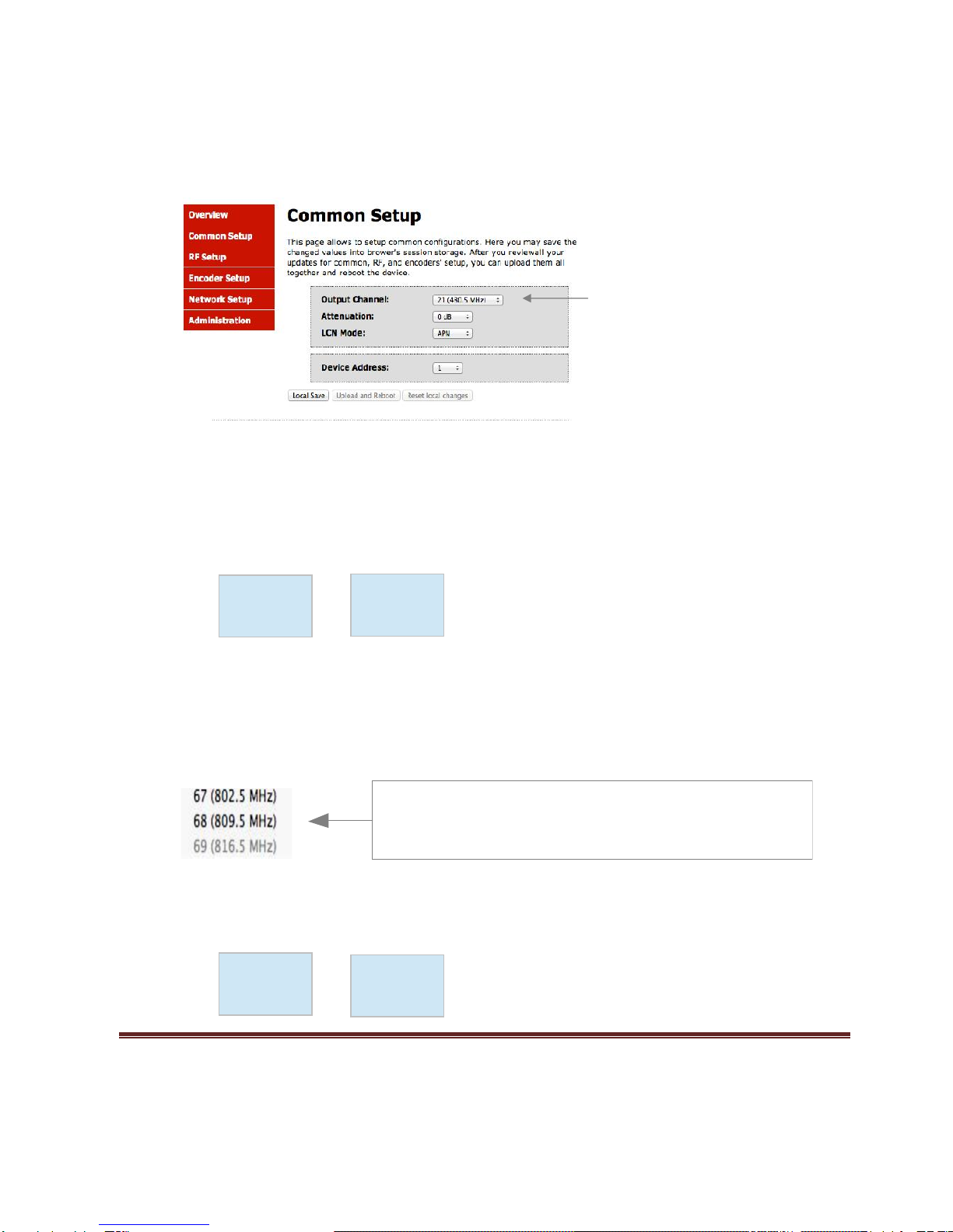
Step 3: Common Setup Tab
Common Setup
Use the Common Setup Page to set the Output channel, Attenuation, LCN Mode, and Device Address.
Step 4: Local Save
Once all parameters are set you are required to do a Local Save.
Notes on Changes:
Changes made to an individual setup tab may require the installer to perform a Local Save AND Upload
and Reboot to the device if you are only making changes to one parameter to the encoder.
Example: Installer is required to change only the output channel for the device (No other changes to the
device are not required). Once the channel has been changed, the installer is required to perform
1: Local Save and
HD-4001DM User Guide and Install Manual Page 8
2: Upload and Reboot.
Notes on Channel Selection: The image below shows the Output Channel is set to CH # 21.
RF1 will output 1 QAM signal carrying 2 digital audio/video channels (within your device's Bandwidth
settings).
The device will automatically set RF2 to Ch # 22.
Using the above example the Physical Channel Outputs for the Quad Input device would be set: 21.1,
21.2 and 22.1, 22.2.
The below diagram depicts how each input on the Quad Encoder is placed in RF 1 or RF2.
Note: The RF2 Physical Channel Output is determined by the selection of output channel of RF1.
RF1 RF2
CH # 21 CH # 22
Note: The Quad Encoder prevents you from selecting the last channel in the device as the first physical
channel for the device's output channel. Select CH # 68 (809.5MHz) for the output channel and the device
will automatically set RF2 as CH # 69 (816.5MHz).
Setting the Output Channel to CH# 68 would result in the following RF1/RF2 configuration (see below)
RF1 RF2
IN-1
IN-2
IN-3
IN-4
Note: Channel 68 is the last channel accessible to select.
In this example CH # 68 can be selected as RF1 and the device will
automatically set RF2 as CH # 69.
CH # 69 can not be set as RF1
IN-1
IN-2
IN-3
IN-4
HD-4001DM User Guide and Install Manual Page 9
CH # 68 CH # 69
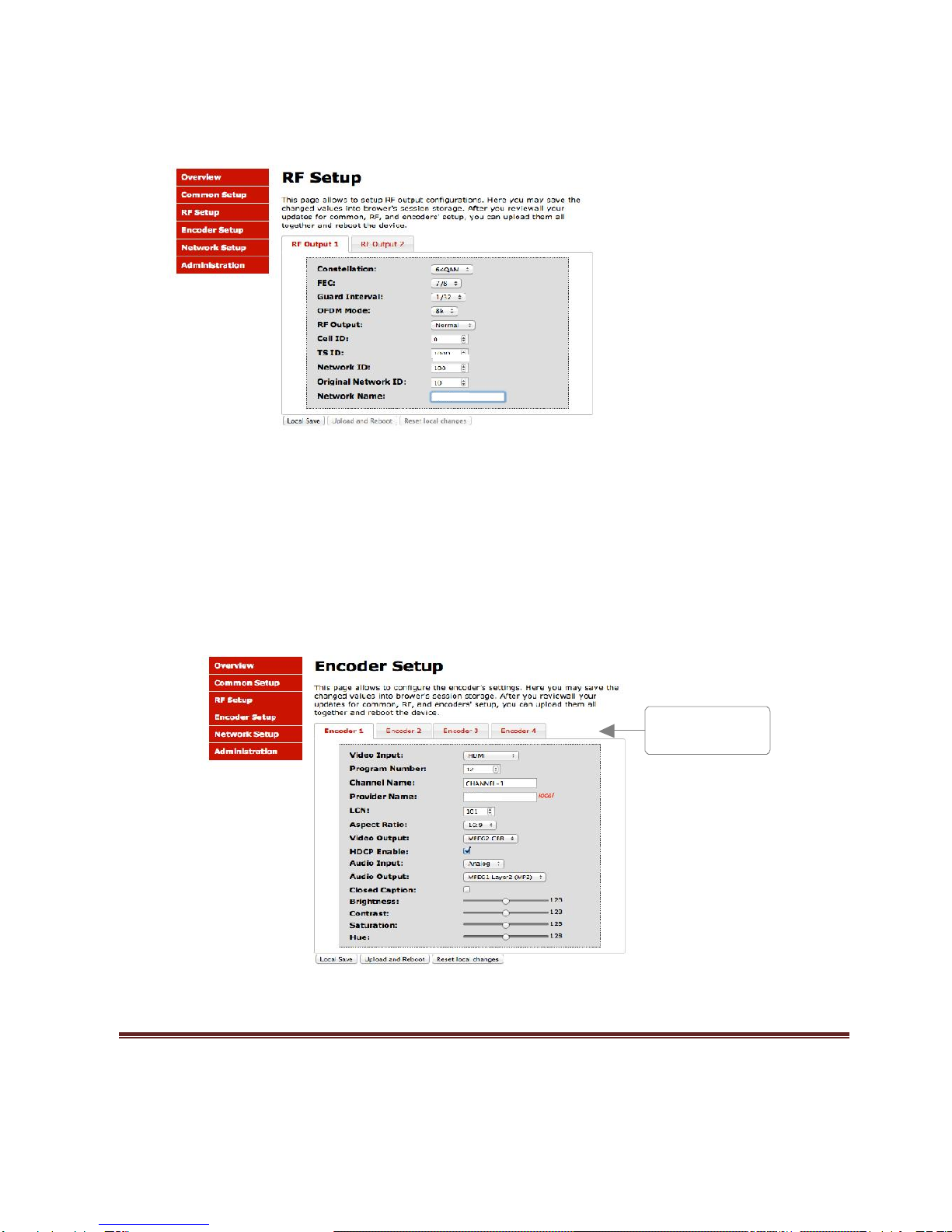
Step 5: RF Setup
RF Setup
Use the RF Setup Page to setup each RF Output.
Select RF Output 1 or RF Output 2.
Select and set the required parameters you require for your installation.
Step 6: Local Save
Once all parameters are set you are required to do a Local Save.
Note: The device shown is a QUAD input device. Your device will not show RF Output 2 if you are setting up a Single or Dual
input encoder.
Step 7: Encoder Setup
Encoder Setup
Select the Encoder 1, 2, 3, 4 tab to program an individual encoder. Select and change all desired
parameters.
Select Encoder for individual
Encoder programming

HD-4001DM User Guide and Install Manual Page 10
NOTE: There will be an Encoder tab present for each input on the device.
Step 8: Local Save for each Encoder tab
Once all parameters are set you are required to do a Local Save on EACH Encoder Tab where
changes were performed.
***** Ensure all Encoder tab changes have been locally saved before performing the next step.
***** Ensure all Encoder changes have been locally saved before performing Step 9.
Step 9: Upload and Reboot
Once you have set all the encoder settings and performed a Local Save for each encoder
Select “Upload and Reboot” after you have saved all your Local changes on each Tab. This
function will upload and save all parameters set in the Common, RF, and Encoder sections of the device.
We highly recommend you save your encoder configuration files. See Administration tab
for how to back you device settings.
Note: Local Save function
will indicate the local changes
made
Upload and Reboot after all
changes have been made and a
Local Save performed
Table of contents


