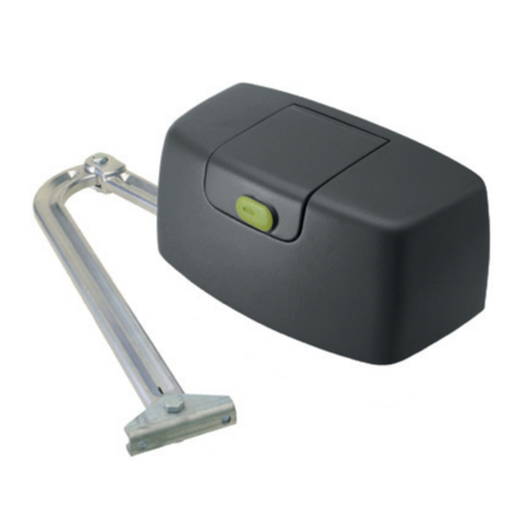
Real Fremont Outswing Opener User manual

Fremont Outswing Opener
Installation Manual

It is recommended that you have a low voltage electrician, or trade
member familiar with garage door installations to install the
operator. You may call us or the manufacturer to see if there is
anyone in your area familiar with the Fremont Opener. Real
Carriage Door & Sliding Hardware is not liable for any damage that
occurs during install, and replacements are the sole responsibility
of the installer and customer. The manufacturer does carry a
warranty for any defects or issues that are from manufacturing
only and will have to be tested by the manufacturer’s technical
team before sending replacements.
It is also a good idea to install a surge protector to avoid any
damage to the operator. The operator can be damaged by power
surges or faulty wiring.
CAUTION
All California residents must have a battery backup installed with
electronic door openers according to Senate Bill No. 969. Please call
our main line for assistance or check out our website for additional
information.
Thank you for choosing Real Sliding Hardware for your project!
We manufacture the highest quality doors and hardware out of the best raw materials in the
USA.
We stand behind our products and are committed to providing an enjoyable customer
experience.
For assistance, please contact our Customer Service Department.
Customer Service: 1-253-853-3815 or 1‐800‐694‐5977
www.realslidinghardware.com

Table of Contents
Packaging ........................................................................................................................4
Specications ..................................................................................................................6
• Motor Carriage.....................................................................................................................................................................8
• Control Unit ..........................................................................................................................................................................10
System Overview..............................................................................................................12
Installation Instructions....................................................................................................14
• Connecting the rails............................................................................................................................................................14
• Chain Tensioner ................................................................................................................................................................. 14
• Wire Connector.................................................................................................................................................................... 15
• Ceiling Bracket.....................................................................................................................................................................16
• Attaching the Swing Arm Fitting......................................................................................................................................16
• Header Brackets..................................................................................................................................................................17
• Push Rods ............................................................................................................................................................................18
• Mounting Control Unit........................................................................................................................................................19
• Inserting ACCU (battery backup) .....................................................................................................................................20
Photo Eyes .......................................................................................................................21
Autoset Programming ......................................................................................................22
• Red Limit Stop ..................................................................................................................................................................... 22
• Autoset..................................................................................................................................................................................23
After Autoset Completion .................................................................................................24
• Battery Pack (ACCU) Installation ..................................................................................................................................... 24
• Adjusting the Close Limit ..................................................................................................................................................24
• Troubleshooting.................................................................................................................................................................. 24
Accessories .....................................................................................................................25
• Remotes ...............................................................................................................................................................................25
• Homelink...............................................................................................................................................................................25
• Battery Pack.........................................................................................................................................................................26
• MEMO....................................................................................................................................................................................26
• SOMLINK ..............................................................................................................................................................................26
• SOMweb............................................................................................................................................................................... 27
• SENSO...................................................................................................................................................................................27
• Outdoor Keypad ..................................................................................................................................................................27
• Wireless Wall Control .........................................................................................................................................................28
Maintenance and Care......................................................................................................28

Page 4 Packaging and Parts
Real Carriage Door & Sliding Hardware Copyright 2020© all rights reserved
Packaging and Parts
The Fremont Opener will ship out in multiple
packages. Weight and size will vary depending on
order.
The main package is for your base kit:
• Shipping Dimensions are 44.5”x 7.5” x 5”
• Weight is approximately 30lbs
The kit includes the following parts:
• Control Unit (1)
• Main track pre-assembled with limit stop chain
and motor carriage (2)
• Isolator (pre-assembled on chain) (2.1)
• Connecting sleeve x2 (3)
• Additional track pieces (4)
• Chain tensioner (for closing end of track) (5)
• Wire Connector (open end of track) (5.1)
• Ceiling bracket which is 2 parts (6)
• Ceiling bracket hardware (7)
• 2 bolts M8 x 20 (wrench size ½”) with two self-
locking nuts M8 (8)
• Door Arm (9) Note: not needed for Fremont
application
• Curved door arm (10) Note: not needed for
Fremont application
• Header bracket with pin and 2 locking c-clips
(11)
• 2 screws 8 x 60mm (wrench size ½”) and 2
washers 5/16” for the attachment to header
(12)
• 2 pins with locking c-clip for door arms Note:
not needed (13)
• Emergency release handle (14)
• Door bracket Note: not needed (15)
• Self-drilling screws ¼” (wrench size 3/8”) for the
door bracket Note: not needed (16)
• Transmitter or remote which is preprogrammed
to your opener (17)

Page 5Packaging and Parts
Real Carriage Door & Sliding Hardware Copyright 2020© all rights reserved
• Warning label (18)
• Warning label for emergency release (19)
• Sommer (manufacturer’s) installation manual:
do not use for install (20)
• Photo Eyes
-2 wires at 32’ 9” long (1)
-1 transmitter photo eye (green sticker) (2)
-1 receiver photo eye (red sticker) (3)
-1 mounting bracket left (4)
-1 mounting bracket (right) (5)
-2 wing nuts M6 (6)
-2 carriage bolts M6 (7)
-4 screws 3/8” (8)
Note: Weights will vary based on additional
hardware that is ordered. The weight is per 9ft
section of rail with motor and control unit housing.
This does not include push rod
weight for the Fremont, or other
hardware attachments.
Push Rods
For a standard up to 9ft opening
the push rods are packaged in
a tube with the dimensions 95”
x 2” x 2”
Note: The length will increase
based on your opening size and
may be shipped freight.
Additional Parts Box
This box includes additional
items needed for your swing
out application. The package
dimensions are 15” x 12” x 3”
This box will include:
• Secondary remote for your
convenience. Keep this remote separate from
the one included in the main box. This remote is
not programmed to the opener yet.
• Fremont Parts Bag or Swing Arm Fittings
-(1) U-Fittings (2)
-(2) Door Bracket (2)
-(3) Pin 1-1/4” x 3-3/4” (2)
-(4) C-clip .375” (2)
-(5) Ring spacer ¾” (2)
-(6) Double threaded
bolt 2.375” x .375” (1)
• Additional Header bracket
(11)
• Swing arm tting
• Battery Backup (optional
except for CA residents)
Note: Any additional accessories ordered will be
included in this box.
When unpacking, make sure that all items are
included in the packages. If anything is missing,
contact us. The actual content may vary depending
on the specic order.

Page 6 Specications
Real Carriage Door & Sliding Hardware Copyright 2020© all rights reserved
Specications
The control board has a motor brake function,
meaning if the motor speed is exceeded, the motor
brake actively uses the brake resistor. There are
also terminals that allow you to hook up to your
home automation system. Force process and
positions are always known by the control unit,
and any changes (attempted break in) will be
recognized. Because of the learn mode (autoset),
the motor will learn the force required to move the
door. This means the operator will not run at full
strength (unless needed), but instead adapts to your
application. With this operator there is only one limit
switch that needs to be installed, and the motor
carriage is simply laid out and pre-installed on the
rails.
Note: For additional information please visit the
manufacturer’s (Sommer) manual.
• Troubleshooting page 62
• Warranty information page 67
• Ceiling mounting and position page 24
Technical
Data
2060 pro+ 2080 pro+ 2110
pro+
Rated voltage 24V DC
Rated
frequency
60 Hz
Number of
programma-
ble remote
buttons
40
Duty cycle 40 %
Emission
value
according
to operating
environment
< 59 dBA – opener only
IP code NEMA1 IP21
Protection
class
class 2
Standard
door height
7’ and 8’ doors (< 2
750 mm)
Max. door
height with
extensions
24 ft. (up to 2 x 3.59 ft. 3 x 3.59
ft. 4 x 3.59 ft.) (7.10 m / up to 2 x
1096 mm 3 x 1096 mm 4 x 1096
mm)
Technical
Data
2060 pro+ 2080 pro+ 2110
pro+
Speed * 9.4 inch/
sec. (240
mm/s)
8.3 inch/
sec. (210
mm/s)
7.4
inch/
sec.
(120
mm/s)
Max. traction
and pressure
force
600 N
(0.75 HP)
800 N (1
HP)
1100
N (1.25
HP)
Max. current
consumption
**
1.0 A 1.3 A 1.5 A
Standby < 3 W
Channels
LED Radio channel Function
1 CH 1 Pulse Mode
2 CH 2 Partial
Opening
or lighting
function
3 CH 3 Dened OPEN
4 CH 4 Dened
CLOSED
The standard setup (without extra memory) can
memorize up to 40 commands, and each channel
utilizes 10 of those. If all 4 channels are used you
can have up to 10 remotes.

Page 7Specications
Real Carriage Door & Sliding Hardware Copyright 2020© all rights reserved
Dip Switches
Dip Switch ON OFF
1 Automatic
closing
activated
Automatic
closing
deactivated
2 Partial
opening active
Illumination
function
3 Side-opening
sectional door
Sectional door
4Retractable
door
Sectional door
Reset Button
The length of time the reset button is pressed will
dene what is reset see below options.
• 1-2 seconds will reset the safety devices
• 5 seconds the force values will be deleted
• 10 seconds the end position (or close) will be
deleted
• 30 seconds will be full factory reset

Page 8 Specications
Real Carriage Door & Sliding Hardware Copyright 2020© all rights reserved
Motor Carriage
Control
Board
Number
Connection Options
1LED CH 1-4 (red) display for radio
channel
2 Magnetic slot (green) lock terminal
3 Limit switch terminal (OPEN) limit
(blue)
4PCB label
5 LEDs opener lighting
6MEMO slot MEMO terminal
7USART slot interface
8 BUZZER slot (black) Warning or
alarm buzzer terminal
9SENSO slot SENSO terminal
10 LASER slot (white) Parking position
laser sensor terminal
11 Terminal for safety contact strip 8k2/
OSE
12 Terminal for wicket door contact
potential free
13 Status LED (green)
14 Reset button (green)
15 DIP switches
16 Radio button (red)

Page 9Specications
Real Carriage Door & Sliding Hardware Copyright 2020© all rights reserved
Connection options for Motor Carriage
Function/application
example
Magnetic slot (green),
lock terminal, Locking
magnet
MOTION slot (white)
terminal for movement
sensor 3-pin
MEMO slot, Memo
terminal, memory
expansion for 450
transmitter commands
USART slot, terminal
e.g. module, home
automation
SENSO slot, terminal
for SENSO, humidity
sensor
BUZZER slot (black),
terminal for warning/
alarm buzzer
LASER slot (white),
terminal for parking
position sensor
Safety contact strip 8k2
terminal
OSE safety contact
strip terminal, +12V =
br, OSE = gn, GND = wh
Wicket door fuse
terminal, contact
command, (12V/10mA)
normally closed
contact, potential free
Output 12V/DC, max
100mA, +12 V, GND =
WH, power supply for
optional accessories,
nger scanner or
external lighting

Page 10 Specications
Real Carriage Door & Sliding Hardware Copyright 2020© all rights reserved
Control Unit
Control
Board
Number
Connection Options
1 DIP switches
2 ACCU slot Terminal for battery pack
3 Keypad (black) Terminal for button
connector cable of the wall control
unit
4Terminal for relay
52-pin Terminal power supply 120 V
AC 50/60 hz
62-pin Terminal Transformer primary
side 120 V AC 50/60 Hz
7 2-pin Terminal 24 V AC Transformer
secondary side
8 PCB label
9 2-pin Terminal Chain and Track 24
V AC
10 Light slot (white) Terminal for Lumi+
supplementary lighting
11 2-pin Terminal Safety Sensors
12 2-pin Terminal wall station or wall
button
Table of contents