RCF DP 1420EN User manual

USER MANUAL
MANUALE D’USO
DP 1420EN ALUMINIUM SOUND
PROJECTOR IN
COMPLIANCE WITH EN
54-24 STANDARD
PROIETTORE DI
SUONO IN ALLUMINIO
CONFORME ALLA
NORMA EN 54-24

TABLE OF CONTENTS
INDICE
ENGLISH
SAFETY PRECAUTIONS
DESCRIPTION
INSTALLATION
CONNECTION
NOTES ABOUT CONSTANT VOLTAGE SYSTEMS
SPECIFICATIONS
ITALIANO
AVVERTENZE PER LA SICUREZZA E PRECAUZIONI D’USO
DESCRIZIONE
INSTALLAZIONE
COLLEGAMENTO
NOTE SUI SISTEMI A TENSIONE COSTANTE
DATI TECNICI
3
5
6
7
9
10
11
13
14
15
17
18

3
ENGLISH
SAFETY PRECAUTIONS
IMPORTANT NOTES
IMPORTANT NOTES
Before connecting and using this product, please read this instruction manual
carefully and keep it on hand for future reference. This manual is to be
considered an integral part of this product and must accompany it when it
changes ownership as a reference for correct installation and use as well as
for the safety precautions.
RCF S.p.A. will not assume any responsibility for the incorrect installation and
/ or use of this product.
SAFETY PRECAUTIONS
1. All the precautions, in particular the safety ones, must be read with special
attention, as they provide important information.
2. Loudspeaker lines (amplifier outputs) can have a sufficiently high voltage
(i.e. 100-70 V) to involve a risk of electrocution: never install or connect this
loudspeaker when the line is alive.
3. Make sure all connections have been made correctly and the loudspeaker
input voltage is suitable for the amplifier output.
4. Protect loudspeaker lines from damage. Make sure they are positioned in a
way that they cannot be stepped on or crushed by objects.
5. Make sure that no objects or liquids can get into this product, as this may
cause a short circuit.
6. Never attempt to carry out any operations, modifications or repairs that
are not expressly described in this manual.
Contact your authorized service centre or qualified personnel should any of
the following occur:
-The loudspeaker does not function (or works in an anomalous way).
-The cable has been damaged.
-Objects or liquids have got into the unit.
-The loudspeaker has been damaged due to heavy impacts or fire.
7. Should the loudspeaker emit any strange odours or smoke, remove it from
the line after having immediately switched the amplifier off.
8. Do not connect this product to any equipment or accessories not foreseen.
For suspended installation, only use the dedicated anchoring points and do
not try to hang this loudspeaker by using elements that are unsuitable or not
specific for this purpose.
Also check the suitability of the support surface to which the product
is anchored (wall, ceiling, structure, etc.) and the components used for
attachment (wall plugs, screws, brackets not supplied by RCF etc.), which
must guarantee the security of the system / installation over time, also
considering, for example, the mechanical vibrations normally generated by
transducers.

4
ENGLISH
9. RCF S.p.A. strongly recommends this product is only installed by
professional qualified installers (or specialised firms) who can ensure a
correct installation and certify it according to the regulations in force.
The entire audio system must comply with the current standards and
regulations regarding electrical systems.
10. Mechanical and electrical factors need to be considered when installing
a professional audio system (in addition to those which are strictly acoustic,
such as sound pressure, angles of coverage, frequency response, etc.).
11. Hearing loss
Exposure to high sound levels can cause permanent hearing loss. The acoustic
pressure level that leads to hearing loss is different from person to person
and depends on the duration of exposure.
To prevent potentially dangerous exposure to high levels of acoustic pressure,
anyone who is exposed to these levels should use adequate protection
devices.
When a transducer capable of producing high sound levels is being used, it is
necessary to wear ear plugs or protective earphones.
See the technical specifications in the instruction manual for the maximum
sound pressure the loudspeaker is capable of producing.
12. To ensure a correct sound reproduction, loudspeaker phase is to be
respected (loudspeakers are connected respecting the amplifier polarity).
This is important when loudspeakers are installed adjacent one another, for
instance, in the same room.
13. To prevent inductive effects from causing hum, noise and a bad system
working, loudspeaker lines should not be laid together with other electric
cables (mains), microphone or line level signal cables connected to amplifier
inputs.
14. The loudspeaker cable shall have wires with a suitable section (twisted,
if possible, to reduce inductive effects due to surrounding electro-magnetic
fields) and a sufficient electrical insulation. Refer to local regulations since
there may be additional requirements about cable characteristics.
15. Install this loudspeaker far from any heat source.
16. Do not use solvents, alcohol, benzene or other volatile substances for
cleaning the external parts of this product. Use a dry cloth.

5
ENGLISH
DP 1420EN is an aluminium sound projector in compliance with EN 54-24
standard.
Main features:
-130 mm (5”) loudspeaker
-Cylindrical extremely sturdy body in extruded aluminium
-It can be installed both indoors and outdoors, thanks to its IP 66 protection
grade
-Equipped with transformer for 70 V / 100 V constant voltage lines
-Internal power setting
-Two ceramic terminal strips for input and output cable connections
-Earth contact
-Thermal fuse that prevents damages to the audio line due to heat on the
loudspeaker
-Orientable wall-mount bracket
-Excellent speech and music reproduction
-High acoustic performance
-Colour: ‘Light Grey’ (RAL 7035).
Sound projectors can be easily pointed in any direction and can be used in
sounds systems with large spaces, for instance supermarkets, railway stations,
undergrounds, factories, warehouses, etc. and in all environments that need a
good sound quality and high efficiency.
DESCRIPTION
RCF S.P.A. THANKS YOU FOR PURCHASING THIS PRODUCT, WHICH
HAS BEEN DESIGNED TO GUARANTEE RELIABILITY AND HIGH
PERFORMANCE.

6
ENGLISH
WARNING: Make sure that the loudspeaker is installed in a stable and
secure way in order to avoid any conditions that may be dangerous for
persons or structures.
Ensure the support surface (walls, ceilings, etc.) has the necessary mechanical
characteristics to support the weight of the loudspeaker.
Before installing the loudspeaker, carefully check all components to be used
and make sure there is no damage, deformation, corrosion and/or missing or
damaged parts that could reduce the safety of the installation.
This loudspeaker can be installed both indoors and outdoors.
INSTALLATION
Make connections as described in the next
manual section.
Mount the loudspeaker to the wall / ceiling
through the 7 mm holes present on its
mounting bracket.
Point the loudspeaker to the listening area
and fix its position by tightening the two
bolts of its mounting bracket.

7
ENGLISH
Connections with the audio line are made by using
the two ceramic terminal strips situated inside the
sound projector (it is necessary to remove the rear
panel by loosening its four screws).
The IN +/– terminals are used for audio signal
input and the OUT +/– terminals (that are directly
connected to the corresponding IN +/– terminals)
can be used as an output to link additional
loudspeakers in parallel.
1. Insert cables through the two rear cable guides.
2. Connect the negative conductor (–) of the audio
line (which comes from the amplifier terminal
marked –, 0 or COM) to the loudspeaker input
IN –.
3. Connect the positive conductor (+) of the audio
line to the loudspeaker input IN +.
4. Follow the same logic to connect the OUT +/– terminals, which can be
used to link additional loudspeakers in parallel.
CONNECTION
WARNING: loudspeaker connections should be only made by qualified and
experienced personnel having the technical know-how or sufficient specific
instructions to ensure that connections are made correctly and to prevent any
electrical danger.
To prevent any risk of electric shock, do not connect loudspeakers when the
amplifier is switched on. Before turning the system on, check all connections
and make sure there are no accidental short circuits. The entire sound system
shall be designed and installed in compliance with the current local laws and
regulations regarding electrical systems.
TERMINAL STRIP CONNECTION
OUT OUT
IN IN
OUT OUT
IN IN
70V/100V
0
8
ENGLISH
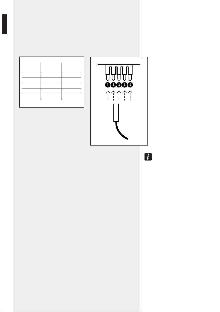
LINE TRANSFORMER CONNECTION
The loudspeaker line transformer is connected to the terminal strips through
the two conductors with FASTON connectors.
Connect the FASTON connector marked TAP (red wire) to the terminal of the
line transformer marked with the desired power.
TAP
1
2
3
4
5
POWER
(100 V)
2.5 W
5 W
10 W
20 W
n.c.
POWER
(70 V)
1.25 W
2.5 W
5 W
10 W
20 W
IMPORTANT NOTES:
-DoNoT remove The FASToN coNNecTor mArkeD COM (blAck wire) From The liNe
TrANSFormer COM TermiNAl.
-DoNoT coNNecT A100 v liNe To The TrANSFormer coNTAcT '5' (20 w – 70 v).
EARTHING THE LOUDSPEAKER
Insert the protective conductor of the local earth system through one of the
rear cable guides and connect it to the terminal strip contact marked with the
earth symbol.
TAP

9
ENGLISH
NOTES ABOUT CONSTANT VOLTAGE SYSTEMS
-The loudspeaker input voltage (Vd) shall correspond to the amplifier output
voltage (Va).
-The sum of nominal power values (Pd x n) of all loudspeakers connected to
the line shall not exceed the amplifier power (Pa).
-Make sure all loudspeakers are connected in phase to ensure a correct
sound reproduction.
-Always use cables having wires with an adequate cross-section, considering
the cable length and the total loudspeaker power.
-Loudspeaker lines must be kept separated from mains cable, microphone
cables or others, in order to avoid inductive phenomena may cause hum
or noises.
-Use loudspeaker cables having twisted wires to reduce hum caused by
inductive effects due to coupling with electromagnetic fields.
AMPLIFIER
Pa = Amplifier power
Pd = Speaker power
n = Number of speakers
Vd = Speaker input voltage
Va = Amplifier output voltage
Pa > Pd x n Va Vd=Va Vd=Va Vd=Va

10
ENGLISH
SPECIFICATIONS
INPUT VOLTAGE:
POWER (SELECTABLE):
INPUT IMPEDANCE:
FREQUENCY RESPONSE:
SENSITIVITY:
MAX. SOUND PRESSURE LEVEL:
COVERAGE ANGLE (– 6 dB):
TRANSDUCER:
BODY MATERIAL:
GRILLE MATERIAL:
BRACKET MATERIAL:
COLOUR:
CONNECTORS:
IP PROTECTION GRADE:
DIMENSIONS:
NET WEIGHT:
OPERATING TEMPERATURE:
100 V – 70 V
20 W – 10 W – 5 W – 2.5 W (100 V)
20 W – 10 W – 5 W – 2.5 W – 1.25 W (70 V)
250 Ω(20 W – 70 V)
500 Ω(20 W – 100 V / 10 W – 70 V)
1 kΩ(10 W – 100 V / 5 W – 70 V)
2 kΩ(5 W – 100 V / 2.5 W – 70 V)
4 kΩ(2.5 W – 100 V / 1.25 W – 70 V)
160 Hz ÷ 20 kHz (–10 dB)
92 dB (1 W, 1 m)
105 dB (20 W, 1 m), 93 dB (20 W, 4 m)
hor.: 254° (500 Hz), 155° (1 kHz), 121° (2 kHz), 62° (4 kHz)
vert.: 254° (500 Hz), 155° (1 kHz), 121° (2 kHz), 62° (4 kHz)
130 mm (5”)
aluminium
aluminium
aluminium
‘Light Grey’ (RAL 7035)
ceramic terminal strips
IP 66
ø 146 mm x 200 mm
2.5 kg
- 40 ÷ + 70 °C (- 40 ÷ + 158 °F)
61.0
Ø 7.0
Ø 146.0
156.0 200.0
Unit: mm
Table of contents
Languages:
Other RCF Speakers System manuals


Popular Speakers System manuals by other brands


Sondpex
Sondpex Active Speaker System and Digital Music... User manual and installation instructions

JVC
JVC NX-PN7 instructions

Marshall Amplification
Marshall Amplification AR-DM61-BT user manual

Yamaha
Yamaha NX-A01 - Speaker Sys Product bulletin

SE Audiotechnik
SE Audiotechnik I-LINE manual

Gemini
Gemini WRX-843 Series user manual