Razorweld KUMJRRW160 User manual

1
Please read and understand this instruction manual carefully
before the installation and operation of this equipment.
OPERATING MANUAL
KUMJRRW160
KUMJRRW200
©
JASIC Technologies America Inc 2013
YEARS Warranty
(Power Source)
3
Razorweld
Razorweld
™™
™
™

2
WARRANTY
• 3 Years from date of purchase.
• JASIC Technologies America Inc Ltd warranties all goods as specified by the manufacturer
of those goods.
• This Warranty does not cover freight or goods that have been interfered with.
• All goods in question must be repaired by an authorised repair agent as appointed by this
company.
• Warranty does not cover abuse, mis-use, accident, theft, general wear and tear.
• New product will not be supplied unless JASIC Technologies America Inc has inspected
product returned for warranty and agree to replace product.
• Product will only be replaced if repair is not possible
• Please view full Warranty term and conditions supplied with machine or at www.razorweld.com
or at the back of this manual.
Thank you for your purchase of your RAZORWELD Welding Machine.
We are proud of our range of welding equipment that has a proven track record of innovation, performance
and reliability. Our product range represents the latest developments in Inverter technology put together
by our professional team of highly skilled engineers. The expertise gained from our long involvement with
inverter technology has proven to be invaluable towards the evolution and future development of our equip-
ment range. This experience gives us the inside knowledge on what the arc characteristics, performance
and interface between man and machine should be. Within our team are specialist welders that have a
proven history of welding knowledge and expertise, giving vital input towards ensuring that our machines
deliver control and performance to the utmost professional level. We employ an expert team of profes-
sional sales, marketing and technical personnel that provide us with market trends, market feedback and
customer comments and requirements. Secondly they provide a customer support service that is second
to none, thus ensuring our customers have condence that they will be well satised both now and in the
future.
RAZORWELD welders are manufactured and compliant with - CAN/CSA E60974-1 &
ANSI/IEC 60974-1, guaranteeing you electrical safety and performance.
California Proposition 65
WARNING: This product contains or produces a chemical known to the State of California to cause cancer
and birth defects (or other reproductive harm) (California Health and Safety Code Section 25249.5 et seq.)
WARNING: This product, when used for welding or cutting, produces fumes or gases which contain chemi-
cals known to the State of California to cause birth defects and, in some cases, cancer (California Health
and Safety Code Section 25249.5 et seq.).
INFORMATION SOURCES
• California Health and Safety Code, Section 25249.4 through 25249.13.
• The California Ofce of Environmental Health Hazard Assessment, 301 Capitol Mall, Sacramento, CA
95814; telephone 916-445-6900.
• California Proposition 65 website: www.oehha.ca.gov/prop65.html.
• American National Standards Institute (ANSI). Product Safety Signs And Labels (ANSI Z535.4), available
from ANSI, 25 West 43rd Street, New York, NY 10036; telephone: 212-642-4900; web site: www.ansi.org.
Razorweld
Razorweld
™
™
™™

3
CONTENTS PAGE
Warranty 2
Safety - Cautions 4-6
Technical Data, Product Information 7-8
weld Program Sequence Control 9-12
Installation & Operation for MMA (Stick) Welding 13-14
MMA (Stick) Welding 15-16
Installation & Operation for DC TIG Welding 17-18
DC TIG Welding, DC Pulse TIG Welding 19-20
Set & Operation for Pulse DC TIG with TIG160/200 21
TIG Welding Fusion and Filler Wire Technique 22
Remote Controls - Installation and Operation 23
Tungsten Electrode Selection & Preparation 24-25
TIG Torch Parts Breakdown 26-27
Trouble Shooting Guide - TIG Welding 28-29
Trouble Shooting Guide - MMA (Stick) Welding 30
Machine Spare Parts Identication 31
Full Warranty Terms 32-34
4
SAFETY
Welding and cutting equipment can be dangerous to both the operator and people in or near the
surrounding working area, if the equipment is not correctly operated. Equipment must only be
used under the strict and comprehensive observance of all relevant safety regulations.
Read and understand this instruction manual carefully before the installation and operation of this
equipment.
• Do not switch the function modes while the machine is operating. Switching of the function modes during
welding can damage the machine. Damage caused in this manner will not be covered under warranty.
• Disconnect the electrode-holder cable from the machine before switching on the machine, to avoid arcing
should the electrode be in contact with the work piece.
• Operators should be trained and or qualied.
Electric shock: It can kill. Touching live electrical parts can cause fatal shocks or severe
burns. The electrode and work circuit is electrically live whenever the output is on. The input
power circuit and internal machine circuits are also live when power is on. In Mig/Mag welding,
the wire, drive rollers, wire feed housing, and all metal parts touching the welding wire are
electrically live. Incorrectly installed or improperly grounded equipment is dangerous.
• Connect the primary input cable according to American standards and regulations. ANSI Z49.1.
• Avoid all contact with live electrical parts of the welding circuit, electrodes and wires with bare hands.
The operator must wear dry welding gloves while he/she performs the welding task.
• The operator should keep the work piece insulated from himself/herself.
• Keep cords dry, free of oil and grease, and protected from hot metal and sparks.
• Frequently inspect input power cable for wear and tear, replace the cable immediately if damaged,
bare wiring is dangerous and can kill.
• Do not use damaged, under sized, or badly joined cables.
• Do not drape cables over your body.
Fumes and gases are dangerous. Smoke and gas generated whilst welding or cutting can
be harmful to people’s health. Welding produces fumes and gases. Breathing these fumes and
gases can be hazardous to your health.
•Do not breathe the smoke and gas generated whilst welding or cutting, keep your head out of the fumes
• Keep the working area well ventilated, use fume extraction or ventilation to remove welding fumes and
gases.
• In conned or heavy fume environments always wear an approved air-supplied respirator.
Welding fumes and gases can displace air and lower the oxygen level causing injury or death. Be sure the
breathing air is safe.
• Do not weld in locations near de-greasing, cleaning, or spraying operations. The heat and rays of the arc
can react with vapours to form highly toxic and irritating gases.
• Materials such as galvanized, lead, or cadmium plated steel, containing elements that can give off toxic
fumes when welded. Do not weld these materials unless the area is very well ventilated, and or wearing
an air supplied respirator.
Arc rays: harmful to people’s eyes and skin. Arc rays from the welding process produce
intense visible and invisible ultraviolet and infrared rays that can burn eyes and skin.
•Always wear a welding helmet with correct shade of lter lens and suitable protective clothing including
welding gloves whilst the welding operation is performed.
•Measures should be taken to protect people in or near the surrounding working area. Use protective
screens or barriers to protect others from ash,glare and sparks; warn others not to watch the arc.
Machine Operating Safety
5
Fire hazard. Welding on closed containers, such as tanks,drums, or pipes, can cause them
to explode. Flying sparks from the welding arc, hot work piece, and hot equipment can cause
res and burns. Accidental contact of electrode to metal objects can cause sparks, explosion,
overheating, or re. Check and be sure the area is safe before doing any welding.
•The welding sparks may cause re, therefore remove any ammable materials away from the working
area, at least 39ft from the welding arc. Cover ammable materials and containers with approved covers
if unable to be moved from the welding area.
• Do not weld on closed containers such as tanks, drums, or pipes, unless they are properly prepared
according to the required Safety Standards to insure that ammable or toxic vapors and substances are
totally removed, these can cause an explosion even though the vessel has been “cleaned”.
Vent hollow castings or containers before heating, cutting or welding. They may explode.
• Do not weld where the atmosphere may contain ammable dust, gas, or liquid vapours (such as petrol)
•Have a re extinguisher nearby and know how to use it. Be alert that welding sparks and hot materials
from welding can easily go through small cracks and openings to adjacent areas. Be aware that welding
on a ceiling, oor, bulkhead, or partition can cause re on the hidden side.
Gas Cylinders. Shielding gas cylinders contain gas under high pressure. If damaged, a cylin-
der can explode. Because gas cylinders are normally part of the welding process, be sure to
treat them carefully. CYLINDERS can explode if damaged.
• Protect gas cylinders from excessive heat, mechanical shocks, physical damage, slag, open ames,
sparks, and arcs.
• Insure cylinders are held secure and upright to prevent tipping or falling over.
• Never allow the welding electrode or earth clamp to touch the gas cylinder, do not drape welding cables
over the cylinder.
• Never weld on a pressurised gas cylinder, it will explode and kill you.
• Open the cylinder valve slowly and turn your face away from the cylinder outlet valve and gas regulator.
Gas build up. The build up of gas can causes a toxic environment, deplete the oxygen content
in the air resulting in death or injury. Many gases use in welding are invisible and odourless.
• Shut off shielding gas supply when not in use.
• Always ventilate conned spaces or use approved air-supplied respirator.
Electronic magnetic elds. MAGNETIC FIELDS can affect Implanted Medical Devices.
•Wearers of Pacemakers and other Implanted Medical Devices should keep away.
•Implanted Medical Device wearers should consult their doctor and the device manufacturer before going
near any electric welding, cutting or heating operation.
Noise can damage hearing. Noise from some processes or equipment can damage hearing.
Wear approved ear protection if noise level is high.
Hot parts. Items being welded generate and hold high heat and can cause severe burns.
Do not touch hot parts with bare hands. Allow a cooling period before working on the welding
gun. Use insulated welding gloves and clothing to handle hot parts and prevent burns.

6
CAUTION
1. Working Environment.
1.1 The environment in which this welding equipment is installed must be free of grinding dust, corrosive
chemicals, ammable gas or materials etc, and at no more than maximum of 80% humidity.
1.2 When using the machine outdoors protect the machine from direct sun light, rain water and snow etc;
the temperature of working environment should be maintained within -14°F to +104°F.
1.3 Keep this equipment 1ft distant from the wall.
1.4 Ensure the working environment is well ventilated.
2. Safety Tips.
2.1 Ventilation
This equipment is small-sized, compact in structure, and of excellent performance in amperage output.
The fan is used to dissipate heat generated by this equipment during the welding operation.
Important: Maintain good ventilation of the louvers of this equipment. The minimum distance between
this equipment and any other objects in or near the working area should be 1ft. Good ventilation is
of critical importance for the normal performance and service life of this equipment.
2.2 Thermal Overload protection.
Should the machine be used to an excessive level, or in high temperature environment, poorly
ventilated area or if the fan malfunctions the Thermal Overload Switch will be activated and the
machine will cease to operate. Under this circumstance, leave the machine switched on to keep the
built-in fan working to bring down the temperature inside the equipment. The machine will be ready for
use again when the internal temperature reaches safe level.
2.3 Over-Voltage Supply
Regarding the power supply voltage range of the machine, please refer to “Main parameter” table.
This equipment is of automatic voltage compensation, which enables the maintaining of the voltage
range within the given range. In case that the voltage of input power supply amperage exceeds the
stipulated value, it is possible to cause damage to the components of this equipment. Please ensure
your primary power supply is correct.
2.4 Do not come into contact with the output terminals while the machine is in operation. An electric shock
may possibly occur.
MAINTENANCE
Exposure to extremely dusty, damp, or corrosive air is damaging to the welding machine. In order to pre-
vent any possible failure or fault of this welding equipment, clean the dust at regular intervals with clean and
dry compressed air of required pressure.
Please note that: lack of maintenance can result in the cancellation of the guarantee; the guarantee of
this welding equipment will be void if the machine has been modied, attempt to take apart the machine or
open the factory-made sealing of the machine without the consent of an authorized representative of the
manufacturer.
TROUBLE SHOOTING
Caution: Only qualied technicians are authorized to undertake the repair of this welding equipment.
For your safety and to avoid Electrical Shock, please observe all safety notes and precautions
detailed in this manual.
Note:
Minimum Motor Generator Power Suggested:- 9KVA
• Our equipment as described in this manual conforms to all applicable rules and regulations of the
‘LowVoltage Directive’ (European Council Directive 73/23/EEC) as set out and amended by Council
Directive 93/68/EEC) and to the National legislation for the enforcement of this Directive.
• Our equipment as described in this manual conforms to all applicable rules and regulations of the
European Council Directive 89/336/EEC, (EMC Directive) and to the National legislation for he
enforcement of this Directive.
7
Technical Data
Power Supply / Phases (V-Ph) 115V/230V - 1 ±15%
Rated Input Power (KVA) 7
ieff (Amps) 14.2A 115V - 13.2A 230V
Imax (Amps) 23A 115V - 23A 230V
Rated Output 140A/25.6V MMA - 160A/16.4V TIG
Welding Current Range 10 ~ 160A
No-Load Voltage (V) 65
Duty Cycle @ 104ºF 35%@140Amps TIG-230V
35%@100Amps TIG-115V
Duty Cycle @ 104ºF 35%@140Amps MMA-230V
35%@80Amps MMA-115V
Protection Class IP21S
Size (inches) 14.4” x 5.3” x 10.9”
Weight (pounds) 13.0
Warranty 3 years on power source
Features
• Latest IGBT Inverter Technology
• Digital Weld Program Sequence Control
• DC TIG (DC tungsten inert gas welding)
- HF Arc Ignition (prevents tungsten inclusion & tungsten damage)
- Adjustable Pulse Frequency 0.5 - 200Hz
- Peak Current, Base Current and Pulse Width Adjustment
- 2/4T Trigger + Spot Time Adjustment
- Start & Final Current Adjustment
- Pre and Post Gas Flow Adjustment
- Up and Down Slope Adjustment
- Remote Torch Amp Control
• MMA (stick electrode)
- Arc Ignition
- Arc Force
• Digital Display
• Thermal Overload Protection
• Generator compatible (recommend 7.0KVA minimum)
Overview
The RAZOR160 is an inverter-based Digital Controlled DC Tig welding machine with HF arc ignition and pulse capability. Produced
using the latest in IGBT technology this machine offers simple easy step by step digital setting of functions and parameters providing
you with professional and complete control. The HF arc ignition provides pre gas and instant arc ignition with the press of the torch
switch leaving no tungsten inclusion and no contamination of the tungsten electrode. Digital set of Pre Gas Time, Start Current Level,
Up Slope Time, Down Slope Time, Finish Current Level and Post Gas Time combined with the choice of 2 or 4T trigger function allows
you to control the start and finish of the weld process at the highest professional level. The Digital Control Pulse Frequency allows full
parameter setting of Peak Current, Base Current, Pulse Frequency and Pulse Width, allowing to manipulate the heat input to the work,
control penetration and minimise distortion. Combining the functions of the RAZOR160 ensures comprehensive control of the welding
parameters when welding all DC weldable materials to produce high quality Tig welds. Our unique Torch Remote Control Interface pro-
vides remote amperage control from the torch in both static and live welding modes. The DC MMA welding function delivers a smooth
and stable arc allowing easy welding with electrodes obtaining high quality welds including cast Iron, stainless and low hydrogen. The
added bonus of Arc Ignition and Arc Force control allows you to set the ideal arc condition no matter what electrode you choose.
The RAZOR160 is a professional machine that is suitable for multiple applications; stainless steel fabrication, dairy & food industry, site
welding, repair and maintenance applications.
Built to our specification and manufactured in compliance to CAN/CSA E60974-1 & ANSI/IEC 60974-1
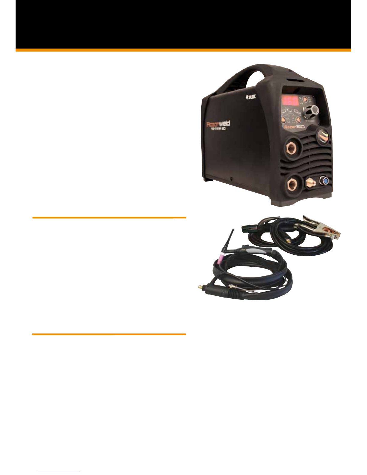
Product Code: KUMJRRW160
Standard Package includes: RAZOR TIG160, SR17 13ft Pro-Grip Lite TIG torch, 13ft Arc Lead Set, Argon regulator, Carry Bag,
Power Adaptor.
DIGITAL DC INVERTER WELDER
TIG/MMA - 160 Amp DC Inverter Welder
Welds: Steels, Stainless, Cast Iron, Bronze, Copper
KUMJRRW160

8
Technical Data
Power Supply / Phases (V-Ph) 240V - 1 ±15%
Rated Input Power (KVA) 9KVA -230V / 5KVA -115V
ieff (Amps) 14.6
Rated Input Current (A) 20.0
Rated Output 10-160A/26.4V MMA
05-200A/18.0V TIG
No-Load Voltage (V) 43
Duty Cycle @ 104ºC TIG 35%@200 Amps 230V
35%@140 Amps 115V
Duty Cycle @ 104ºC MMA 35%@180 Amps 230V
35%@120 Amps 115V
Efficiency (%) 85
Power Factor 0.70
Protection Class IP21S
Insulation Class F
Size (mm) 14.4 x 5.3 x 10.9”
Weight (pounds) 13.5
Warranty 3 years on power source
Features
• Latest IGBT Inverter Technology
• Digital Weld Program Sequence Control
• DC TIG (DC tungsten inert gas welding)
- HF Arc Ignition (prevents tungsten inclusion & tungsten damage)
- Adjustable Pulse Frequency 0.5 - 200Hz
- Peak Current, Base Current and Pulse Width Adjustment
- 2/4T Trigger + Spot Time Adjustment
- Start & Final Current Adjustment
- Pre and Post Gas Flow Adjustment
- Up and Down Slope Adjustment
- Remote Torch Amp Control
• MMA (stick electrode)
- Arc Ignition
- Arc Force
• Digital Display
• Thermal Overload Protection
• Generator compatible (recommend 9.0KVA 230V)
Overview
The RAZOR200 is an inverter-based Digital Controlled DC Tig welding machine with HF arc ignition and pulse capability. Produced
using the latest in IGBT technology this machine offers simple easy step by step digital setting of functions and parameters providing
you with professional and complete control. The HF arc ignition provides pre gas and instant arc ignition with the press of the torch
switch leaving no tungsten inclusion and no contamination of the tungsten electrode. Digital set of Pre Gas Time, Start Current Level,
Up Slope Time, Down Slope Time, Finish Current Level and Post Gas Time combined with the choice of 2 or 4T trigger function allows
you to control the start and finish of the weld process at the highest professional level. The Digital Control Pulse Frequency allows full
parameter setting of Peak Current, Base Current, Pulse Frequency and Pulse Width, allowing to manipulate the heat input to the work,
control penetration and minimise distortion. Combining the functions of the RAZOR200 ensures comprehensive control of the welding
parameters when welding all DC weldable materials to produce high quality Tig welds. Our unique Torch Remote Control Interface pro-
vides remote amperage control from the torch in both static and live welding modes. The DC MMA welding function delivers a smooth
and stable arc allowing easy welding with electrodes obtaining high quality welds including cast Iron, stainless and low hydrogen. The
added bonus of Arc Ignition and Arc Force control allows you to set the ideal arc condition no matter what electrode you choose.
The RAZOR200 is a professional machine that is suitable for multiple applications; stainless steel fabrication, dairy & food industry, site
welding, repair and maintenance applications.
Built to our specification and manufactured in compliance to CAN/CSA E60974-1 & ANSI/IEC 60974-1
Product Code: KUMJRRW200
Standard Package includes: RAZOR200 Machine, SR26 x 13Ft Tig Torch, 13Ft Arc Lead set, Argon Regulator
DIGITAL DC INVERTER WELDER
TIG/MMA - 200 Amp DC Inverter Welder
Welds: Steels, Stainless, Cast Iron, Bronze, Copper
KUMJRRW200

9
43
1
Indicates Action
Selector Pad
2
2. Encoder Knob - provides digital adjustment of welding parameters.
The Encoder Knob is used to set the value of
the parameters required. Turning the encoder
will adjust the value shown in the digital display
screen.
3. Torch Switch Mode Selector - Controls the on/off cycle of the machine using the torch switch while
incorporating the weld program parameters selections.
2T: Select the 2T icon using the selector pad.
2T uses 2 actions of the torch switch while
incorporating weld program parameter
selections.
(refer to page 11 for instruction of 2T function)
4T: Select the 4T icon using the selector pad.
4T uses 4 actions of the torch switch while
incorporating weld program parameter
selections. 4T provides operator control of the
Start and Finish periods of the weld sequence
(refer to page 12 for instruction of 4T function)
SPOT: Select the SPOT icon using the
selector pad.
Spot uses a single action of the torch switch
1) Pressing the torch switch gives arc igni-
tion and initializes the welding sequence for a
period of time set using the spot timer.
(refer to page 12 for instruction of SPOT
function)
DC Pulse Tig: Select by pushing
selector pad to cycle through to
illuminate the DC Pulse icon.
DC Tig: Select by pushing the
selector button to cycle through to
illuminate the DC icon.
MMA: Select by pushing the
selector button to cycle through to
illuminate the DC icon.
1. Mode Selector - Enables selection of required welding mode - MMA - DC TIG - DC PULSE TIG.
Front Panel Functions
Front Panel Operation - Weld Program Sequence Control

10
Base Amp - Provides selection for the Base Amperage during the Pulse Welding cycle.
Peak Amp - Provides selection for the Maximum Welding Amperage required during welding.
Up Slope Time - Sets the transition time from Start Amperage to Welding Amperage
Start Amp - Provides selection for the amount of amps required at the start of the weld.
Continued - Front Panel Operation - Weld Program Sequence Control
Parameter selection: Select by pushing selector pad to
cycle through to illuminate the icon of the parameter
required. Each push of the selector pad will move the icon
illumination in a clockwise cycle.
Pre Gas Timer - Provides selection for gas ow time prior to the arc starting.
Turn the Encoder to set
the Pre-Gas Time
(Range is 0-10 Sec)
Pre Gas Time: Select by pushing selector
pad to cycle through to illuminate the Pre
Gas Timer icon.
The value selected shows on the digital
display. It is the length of time the gas
will ow before the arc starts.
Indicates Action
Selector Pad
Turn the Encoder to set
the Start Amp value
(Range is 10-200A)
Pre Gas Time: Select by pushing selector
pad to cycle through to illuminate the Start
Amp icon.
The value selected shows on the digital
display. It is the amount of amps the
machine will deliver at the start of the
welding sequence.
Turn the Encoder to set
the Up Slope value
(Range is 0-60 Sec)
Up Slope Time: Select by pushing selector
pad to cycle through to illuminate the
Up Slope icon.
The value selected shows on the digital
display. It is the amount of time the
welding current takes to climb from
start amperage to welding amperage.
Turn the Encoder to set
the Peak Amp value
(Range is 10-200A)
Peak Amp: Select by pushing selector
pad to cycle through to illuminate the Peak
Amp icon.
The value selected shows on the digital
display. It is the maximum set value of
amperage the machine will deliver.
Turn the Encoder to set
the Peak Amp value
(Range is 10-200A)
Base Amp: Select by pushing selector
pad to cycle through to illuminate the Peak
Amp icon.
The value selected shows on the digital
display. It is the set value of amperage
the machine will deliver during the Base
Amp period of the pulse cycle.
4. Weld Program - Provides selection weld program parameters
This manual suits for next models
1
Table of contents
Other Razorweld Welding System manuals

Razorweld
Razorweld JRW145D User manual

Razorweld
Razorweld KUMJRRW145 User manual

Razorweld
Razorweld Xcel-Arc MULTI 230 AC/DC User manual

Razorweld
Razorweld RAZORCUT45 User manual

Razorweld
Razorweld JRW200AC/DC User manual

Razorweld
Razorweld JRWPC45LT User manual

Razorweld
Razorweld Xcel-Arc ARC160 User manual

Razorweld
Razorweld KUMJRRW110DC User manual
Popular Welding System manuals by other brands


TAFA
TAFA 30*8B35 owner's manual

Lincoln Electric
Lincoln Electric INVERTEC V350-PRO CE Technical specifications

ESAB
ESAB Buddy Arc 145 instruction manual

CIGWELD
CIGWELD 636804 use instructions

Red-D-Arc
Red-D-Arc DC-400 Operator's manual

Hobart Welding Products
Hobart Welding Products Spool Gun DP 3035-10 owner's manual


