Raytheon 133-560 Series User manual

Raytheon Marine GmbH
High Seas Products
Postfach 1166
D -- 24100 Kiel
Germany
Tel+49--431--3019--0
Fax+49--431--3019--291
Email [email protected]
www.raytheon--marine.com
R
3649.DOC010102 Edition: July 06, 2005
Repeater Compass
Type 133 -- 560
Operator manual

Weitergabe sowie Vervielfältigung dieser Unterlage, Verwertung und
Mitteilung ihres Inhaltes nicht gestattet, soweit nicht ausdrücklich
zugestanden. Zuwiderhandlungen verpflichten zu Schadenersatz.
Copying of this document, and giving it to others and the use or
communication of the contents thereof, are forbidden without express
authority. Offenders are liable to the payment of damages.
Toute communication ou reproduction de ce document, toute
exploitation ou communication de son contenu sont interdites, sauf
autorisation expresse. Tout manquement à cette règle est illicite et
expose son auteur au versement de dommages et intérêts.
Sin nuestra expresa autorización, queda terminantemente prohibida la
reproducción total o parcial de este documento, así como su uso
indebido y/o su exhibición o comunicación a terceros. De los infractores
se exigirá el correspondiente resarcimiento de daños y perjuicios.

Operator manual REPEATER
133--560
I3649.DOC010102Edition: July 06, 2005
CONTENTS
1 Description 1......................................................
1.1 General 1......................................................................
1.2 Construction 3..................................................................
1.2.1 Front panel 3...................................................................
1.2.2 Stepping motor assembly 4.......................................................
1.3 Principle of operation 5...........................................................
1.3.1 Function keys 6.................................................................
1.4 Technical data 8.................................................................
1.4.1 Dimensions and weight 8.........................................................
1.4.2 Mechanical data 8...............................................................
1.4.3 Electrical data 8.................................................................
1.4.4 Serial Input 8...................................................................
2 Operating of the Repeater Compass Type 133 -- 560 9................
2.1 Indications 9....................................................................
2.1.1 Analog heading indication 9.......................................................
2.1.2 Digital heading display 9..........................................................
2.1.3 Status-- and alarm indications 9...................................................
2.2 Notes on the operating instructions 10...............................................
2.3 Switching on the Repeater Compass 11.............................................
2.4 Indication of the Repeater Compass after putting into operation 12......................
2.5 Indications during GPS compass operation 12........................................
2.6 Signals during operation 13........................................................
2.7 Additional operations during normal mode 14.........................................
2.7.1 Dimming 14......................................................................
2.7.2 Test 15..........................................................................
2.7.3 Correction of the analog indications (cards) 16........................................
2.8 Fault operation 17................................................................
2.9 Service mode 18.................................................................
2.10 Switching off the Repeater Compass 21.............................................
3 Installation of the Repeater Compass 23..............................
3.1 General 23......................................................................
3.1.1 Mounting of the Repeater Compass 23..............................................
3.1.2 Electrical installation of the Repeater Compass 24....................................
3.2 First putting into operation 24......................................................
3.3 Configuration 25..................................................................
3.3.1 General 25......................................................................
3.3.2 Adjustments in the configuration mode (CF) 27.......................................
3.3.3 Adjustment of the course bus parameter 30..........................................
3.3.4 Adjustment of the NMEA telegrams 30..............................................

Operator manual
II
3649.DOC010102 Edition: July 06, 2005
4 Maintenance and shipboard repair 33................................
4.1 Maintenance 33..................................................................
4.2 Shipboard repair 33...............................................................
4.2.1 General 33......................................................................
4.2. 2 Measures in case of alarms on the Repeater Compass 34................................
ANNEX
Drawings:
-- Dimensional Drawing Repeater Compass (standard) (IP23) 133--560.HP005
-- Dimensional Drawing Repeater Compass (bulkhead mounting) (IP44) 133--560.HP005
-- Dimensional Drawing Repeater Compass (wall mounting) +(IP44) 133--560.HP005
-- Dimensional Drawing Repeater Compass (bulkhead mounting) (IP56) 133--560.HP005
-- Dimensional Drawing Repeater Compass (flush mount. + casing) (IP56) 133--560.HP005
-- Dimensional Drawing Repeater Compass (flush mount. + frame) (IP56) 133--560.HP005
Operator manual REPEATER
133--560
1
3649.DOC010102 Edition: July 06, 2005
1 Description
1.1 General
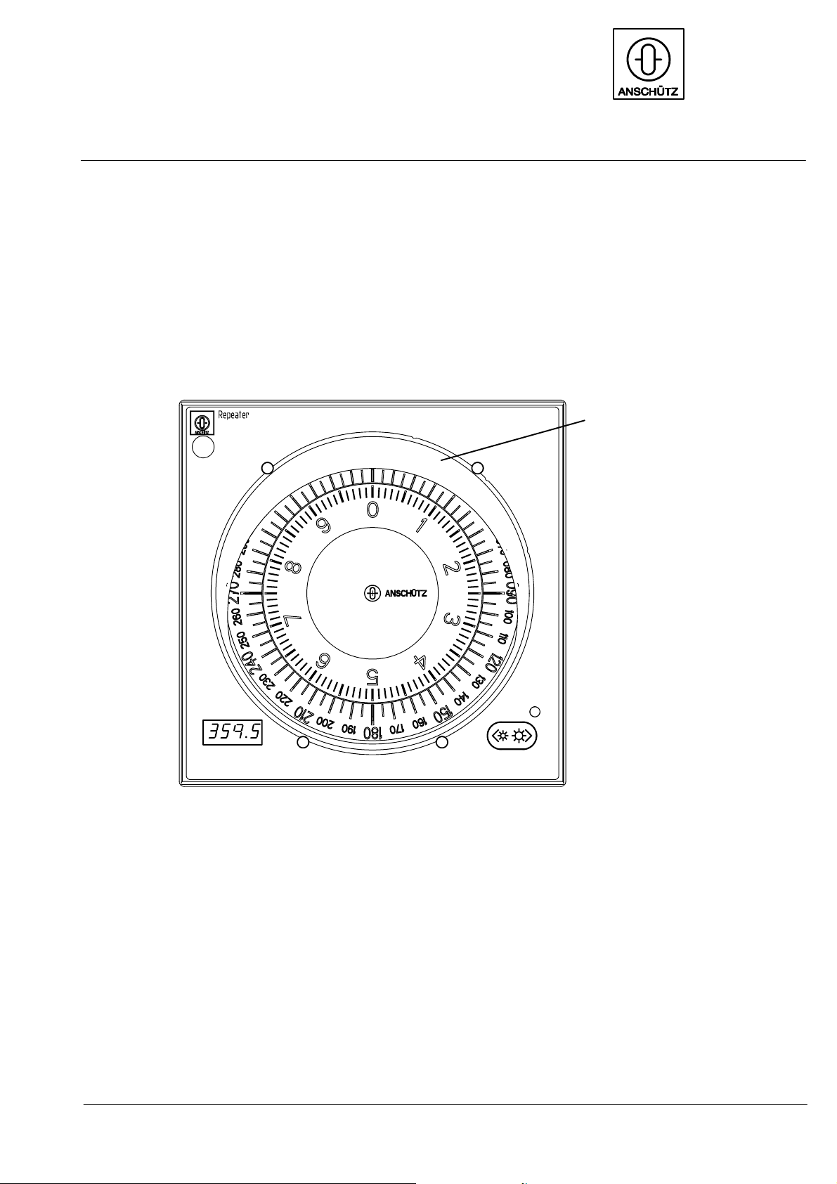
The analog Repeater Compass, Type 133 -- 560, shows the heading determined by the gyro
compass in relation to “GEOGRAPHICAL NORTH”. The course is indicated by a 360°and a
10°card. It receives the heading signal in absolute and clear values from the gyro compass
via a serial interface (RM Course BUS* or NMEA 0183).
anti--glare shield
Fig. 1: View of the front panel of the Repeater Compass
The following versions can be configurated for the different facilities:
-- Steering Repeater Compass for gyro compass equipment
-- Repeater Compass for gyro compass equipment
-- Repeater Compass for magnetic compass equipment
-- Repeater Compass for gyro and magnetic compass equipment
-- Repeater Compass for GPS compass
*) “Raytheon Marine” specific

Operator manual
23649.DOC010102
Edition: July 06, 2005
If the Repeater Compass is used with a gyro and magnetic compass there is no special
adjustment needed.
In any other cases the Repeater Compass has to be configurated (see section 3.3).
The table below describes all types of Repeater Compasses and enclosures:
No. Part No. Drawing No. Designation Type
of
enclo--
sure
2223 133--560 NG001 133--560.HP005 Repeater Compass for flush moun-
ting
(IP23)
2224 133--560 NG003 133--560.HP010 Repeater Compass for bulkhead
mounting
(IP44)
2225 133--560 NG004 133--560.HP011 Repeater Compass for wall mounting (IP44)
2226 133--560 NG005 133--560.HP012 Repeater Compass for bulkhead
mounting
(IP56)
2227 133--560 NG006 133--560.HP013 Repeater Compass for flush moun-
ting + casing
(IP56B)
2228 133--560 NG007 133--560.HP018 Repeater Compass for flush moun-
ting + frame
(IP56B)
The principles of operation and the interfaces of the different types are identical.

Operator manual REPEATER
133--560
3
3649.DOC010102 Edition: July 06, 2005
1.2 Construction
1.2.1 Front panel
An anti--reflective polyester screen covers the cards on the front panel of the Repeater
Compass. The lubber line is inside the plate. LEDs illuminate the lubber line and the cards
in an area of ±55°. In the lower area of the front plate on the right side (refer to Fig. 2) a
LED ligths up in three colors. Below the LED there are two multiple--function keys. On the
left side there is a digital display for the indication of the heading and error messages.
LED
Digital display Multiple--function
keys
360°card
10°card
Fig. 2: Operating and indicating instruments on the front panel of the Repeater Compass

Operator manual
43649.DOC010102
Edition: July 06, 2005
1.2.2 Stepping motor assembly
(Refer to Fig. 3)
The two cards are driven by a stepping motor each. The shaft of the stepping motor for the
10°card is arranged centrically in the shaft of the stepping motor for the 360°card. The
cards are directly mounted on the shafts of the stepping motors. The speed of the two step-
ping motors are in the ratio of 1:36. The 10°card is equipped with a graduation of 1/10°and
the 360°card with a graduation of 5°. Both cards are translucent and lit up around the lub-
ber line by LEDs.
360°card 10°card
Stepping motor
Front panel Steering repeater PCB
Fig. 3: Stepping motor assembly -- section view of the Repeater Compass

Operator manual REPEATER
133--560
5
3649.DOC010102 Edition: July 06, 2005
1.3 Principle of operation
The Repeater Compass receives the heading information from the gyro compass or from
the magnetic compass by means of serial heading transmission with absolute and clear va-
lues. The serial transmission is realized via the RS 422 HEADING SERIAL* interface.
If it is intended to indicate data via an NMEA RS 422 or RS 232 interface, the Repeater
Compass recognizes this type of interface and changes automatically over to gyro / magne-
tic compass operation. Selecting the telegram type via a configuration is not necessary.
The serial course information is converted into steps on the steering repeater PCB for the
stepping motor in the ration of 1 : 36 and is shown by the 360°and the 10°card.
*) “Raytheon Marine” specific

Operator manual
63649.DOC010102
Edition: July 06, 2005
1.3.1 Function keys
Various functions can be selected via two keys on the right side of the front panel:
-- 1. Function: DIMMING (see section 2.7.1)
This function is available in the normal operation mode. It is not specially
indicated. With the ” ” key or the ” ” key the setting can be made
darker or brighter.
-- 2. Function: TEST (see section 2.7.2)
This function is activated by operating the keys ” ” and ” ”
simultaneously for approx. 2s until the display shows .
After releasing both keys, the test runs on its own.
The dimming of all displays and lightings, the completeness of the digital
display and the function of the analog displays is tested.
The test lasts approx. 3s.
By operating the ” ” key the current adjustments and configurations are
shown. (see section 2.9)
-- 3. Function: Can Bus address
The Can bus address mode is activated by operating the keys ” ” and
”” for approx. 5s until the display shows .
-- 4. Function: CONFIGURATION (see section 3.3)
The configuration mode is activated by operating the keys ” ” and ” ”
simultaneously for approx. 10s until is indicated.
By operating the ” ” key the required configuration mode is selected and
can be activated by operating the ” ” key. Active configurations are
flashing; non--active configurations light up permanently.
This manual suits for next models
6
Table of contents


