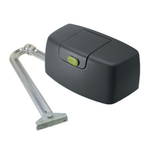
RAMSET RAM 30 30 User manual
RAMSET
www.ramsetinc.com

RAMSET
www.ramsetinc.com

RAM 30-30
1
RAMSET
www.ramsetinc.com
Important Safety Requirements & Instructions...................................................................................1
Responsibilities of Installers and Technicians....................................................................................2
Important Safety Requirements by UL Standards..............................................................................3
Classes of Vehicular Gate Operators.................................................................................................4
General Specifications........................................................................................................................5
Installation Specifications ...................................................................................................................6
Hookup Electrical Power - Gate Travel Adjustment ...........................................................................7
Standard Installation for Gates from 8’ to 16’ in Length .....................................................................7
Standard Installation for Gates from 16’ to 20’ in Length ...................................................................8
Space Required for Standard Gate in the Open Position...................................................................8
Sensor Installation..............................................................................................................................9
Pushbutton Controls & Master/Slave Installation .............................................................................10
Dip Switch Configuration ............................................................................................................ 11-12
Terminal Strip Connections ........................................................................................................ 13-14
Ramset “Intelligate” Control Board ...................................................................................................15
Wire Board Connections...................................................................................................................16
Exploded View Parts Diagram..........................................................................................................17
Bill of Materials ........................................................................................................................... 18-19
Gate Entrance Safety Precautions ...................................................................................................20
Important Information for The Homeowner.......................................................................................21
Troubleshooting Table......................................................................................................................22
Ramset Optional Accessories ..........................................................................................................23
Do not install this gate operator if you do not have experience or appropriate
training with gate operators.
WARNING
WARNING To reduce the risk of injury or death:
1. READ AND FOLLOW ALL INSTRUCTIONS.
2. Never let children operate or play with gate controls.
Keep the remote control away from children.
3. Always keep people and objects away from the gate.
NO ONE SHOULD CROSS THE PATH OF THE MOVING
GATE.
4. Test the Vehicular Gate Operator monthly. The gate
MUST reverse on contact with a rigid object or stop
when an object activates the non-contact sensors.
After adjusting the limit of travel, retest the Vehicular
Gate Operator. Failure to adjust and retest the
Vehicular Gate Operator properly can increase the
risk of injury or death.
5. Use the Emergency Release only when power switch
or circuit breaker has been turned off. Using the Emer-
gency Release during a power failure can be a hazard
if power is abruptly restored.
6. KEEP GATES PROPERLY MAINTAINED. Read the
Owner’s Manual. Have a qualified service person
make repairs to gate hardware.
7. The entrance is for vehicles only. Pedestrians must
use separate entrance.
8. SAVE THESE INSTRUCTIONS.
IMPORTANT SAFETY REQUIREMENTS & INSTRUCTIONS
TABLE OF CONTENTS

2
RAM 30-30
RAMSET
www.ramsetinc.com
INSTALLATION
• READ AND UNDERSTAND THE INSTRUCTION MANUAL BEFORE ATTEMPTING
ANY INSTALLATION.
• DO NOT EXCEED THE EQUIPMENT SPECIFICATIONS.
• INSURE A SAFE AND PROPER INSTALLATION.
• INSTALL THIS EQUIPMENT IN ACCORDANCE WITH THE UL 325 SPECIFICATIONS.
• MAKE SURE TO ELIMINATE ANY PINCH POINTS EXISTING ON THE INSTALLATION.
(ie. ROLLERS, ARMS…etc.)
• RAMSET GATE OPERATORS MUST BE INSTALLED BY A TRAINED TECHNICIAN.
SAFETY DEVICES
• REMOVE OR PROTECT ALL PINCH POINTS FROM THE GATE OPERATOR.
• MAKE SURE EVERY INSTALLATION HAS A MINIMUM OF ONE NON-CONTACT
SAFETY DEVICE (SUCH AS A PHOTO EYE OR LOOP DETECTOR).
• CHECK THE E.R.D. SENSITIVITY FOR PROPER ADJUSTMENTS.
• MAKE SURE THAT ALL AREAS AROUND THE GATE ARE SAFE AND SECURE.
(SUCH AS THE FRONT, REAR, AND TRAVEL AREA).
COMMUNICATE WITH THE END-USER
• INSTRUCT THE END USER ON HOW TO SAFELY OPERATE ALL FUNCTIONS
OF THE OPERATOR.
• INSTRUCT THE END-USER ON HOW TO SAFELY USE THE EMERGENCY
RELEASE.
• CLEARLY LABEL AND IDENTIFY THE CIRCUIT BREAKER FOR THE OPERATOR.
• SHOW THE END-USER THE LOCATION OF THE CIRCUIT BREAKER FOR THE
OPERATOR.
• THOROUGHLY EXPLAIN ANY AND ALL WARRANTIES ASSOCIATED WITH THE
OPERATOR AND INSTALLATION.
• KEEP A COPY OF EACH MANUAL HANDY FOR FUTURE REFERENCES.
• PROVIDE THE END-USER WITH THE “HOME OWNERS MANUAL PACKET”
(INCLUDED WITH EVERY OPERATOR).
RESPONSIBILITIES OF INSTALLERS AND TECHNICIANS

RAM 30-30
3
RAMSET
www.ramsetinc.com
Prior to installation, the following must be
observed: (per UL 325.56.8.4).
a) Install the gate operator only when:
1. The operator is appropriate for the construction of
the gate and the usage Class of the gate,
2. All openings of a horizontal slide gate are guarded
or screened from the bottom of the gate to a mini-
mum of 4 feet (1.22 m) above the ground to prevent
a 2 1/4 inch (57.2 mm) diameter sphere from passing
through the openings anywhere in the gate, and in
that portion of the adjacent fence that the gate covers
in the open position.
3. All exposed pinch points are eliminated or guarded,
and
4. Guarding is supplied for exposed rollers.
b) The operator is intended for installation only on gates
used for vehicles. Pedestrians must be supplied with a
separate access opening. The pedestrian access opening
shall be designed to promote pedestrian usage. Locate
the gate such that persons will not come in contact with
the vehicular gate during the entire path of travel of the
vehicular gate.
c) The gate must be installed in a location so that enough
clearance is supplied between the gate and adjacent
structures when opening and closing to reduce the risk
of entrapment. Swinging gates shall not open into public
access areas.
d) The gate must be properly installed and work freely in
both directions prior to the installation of the gate opera-
tor. Do not over-tighten the operator clutch or pressure
relief valve to compensate for a damaged gate.
e) For gate operators utilizing Type D protection:
1. The gate operator controls must be placed so that
the user has full view of the gate area when the
gate is moving.
2. The placard as required by 58.1.6 shall be placed
adjacent to the controls,
3. An automatic closing device (such as a timer, loop
sensor, or similar device) shall not be employed,
and
4. No other activation device shall be connected.
f) Controls intended for user activation must be located at
least six feet (6’) away from any moving part of the gate
and where the user is prevented from reaching over, un-
der, around or through the gate to operate the controls.
Outdoor or easily accessible controls shall have a security
feature to prevent unauthorized use.
g) The stop and/or reset button must be located in the line-
of-sight of the gate. Activation of the reset control shall not
cause the operator to start.
h) A minimum of two (2) WARNING SIGNS shall be in-
stalled, one on each side of the gate where easily visible.
i) For gate operators utilizing a non-contact sensor in ac-
cordance with UL 31.1.1:
1. See instructions on the placement of non-contact
sensors for each Type of application.
2. Care shall be exercised to reduce the risk of nui-
sance tripping, such as when a vehicle, trips the
sensor while the gate is still moving, and
3. One or more non-contact sensors shall be located
where the risk of entrapment or obstruction exists,
such as the perimeter reachable by a moving gate or
barrier.
j) For a gate operator utilizing a contact sensor in accor-
dance with 31.1.1:
1. One or more contact sensors shall be located where
the risk of entrapment or obstruction exists, such as at
the leading edge, trailing edge, and postmounted both
inside and outside of a vehicular horizontal slide gate.
2. One or more contact sensors shall be located at the
bottom edge of a vehicular vertical lift gate.
3. One or more contact sensors shall be located at the
pinch point of a vehicular vertical pivot gate.
4. A hardwired contact sensor shall be located and its
wiring arranged so that the communication between
the sensor and the gate operator is not subjected to
mechanical damage.
5. A wireless contact sensor such as one that transmits
radio frequency (RF) signals to the gate operator for
entrapment protection functions shall be located where
the transmission of the signals are not obstructed or
impeded by building structures, natural landscap-
ing or similar obstruction. A wireless contact sensor
shall function under the intended end-use conditions.
6. One or more contact sensors shall be located on
the inside and outside leading edge of a swing gate.
Additionally, if the bottom edge of a swing gate is
greater than 6 inches (152 mm) above the ground
at any point in its arc of travel, one or more con-
tact sensors shall be located on the bottom edge.
7. One or more contact sensors shall be located at the
bottom edge of a vertical barrier (arm).
IMPORTANT SAFETY REQUIREMENTS BY UL STANDARDS

4
RAM 30-30
RAMSET
www.ramsetinc.com
Vehicular horizontal slide-gate operator (or system) - A vehicular gate operator (or system) that
controls a gate which slides in a horizontal direction that is intended for use for vehicular entrance or
exit to a drive, parking lot, or the like.
Vehicular swing-gate operator (or system) - A vehicular gate operator (or system) that controls a
gate which swings in an arc in a horizontal plane that is intended for use for vehicular entrance or exit
to a drive, parking lot or the like.
Residential vehicular gate operator-Class I - A vehicular gate operator (or system) intended for
use at a home of one-to four single family dwellings, or a garage or parking area associated there
with.
Commercial/general access vehicular gate operator-Class II - A vehicular gate operator (or sys-
tem) intended for use in a commercial location or building such as a multi-family housing unit (five or
more single family units), hotels, garages, retail stores, or other buildings serving the general public.
Industrial/limited access vehicular gate operator-Class III - A vehicular gate operator (or system)
intended for use in an industrial location or building such as a factory or loading dock area or other
locations not intended to service the general public.
Restricted access vehicular gate operator-Class IV - A vehicular gate operator (or system) in-
tended for use in a guarded industrial location or building such as an airport security area or other re-
stricted access locations not servicing the general public, in which unauthorized access is prevented
via supervision by security personnel.
A 3 wire, 120 VAC electrical circuit with a 15 amps independent circuit breaker for single operator
and a 20 amps for Master/Slave. Low voltage control wires must be run in a separate conduit to the
operator.
NOTE: Always consult and follow all local building and electrical codes prior to installation.
CLASSES OF VEHICULAR GATE OPERATORS
RECOMMENDED ELECTRICAL CONNECTION
RECOMMENDED WIRE GAUGE
AMPERES
INPUT POWER MOTOR HP RUN START
120V Single Phase 3/4 8.0 8.7
220V Single Phase 1 4.7 5.0
MAXIMUM CONDUIT DISTANCE IN FEET
USING COPPER WIRE BY WIRE SIZE
14ga. 12ga. 10ga. 8ga.
Up to 50’ 50-150’ 150-250’ 450’
Up to 100’ 50-350’ 350-650’ 800’
RAM 30-30
5
RAMSET
www.ramsetinc.com
GENERAL SPECIFICATIONS
WARNING Do not exceed the specifications. The warranty on your unit will be void if the
installation exceeds the recommended specifications.
MAXIMUM GATE SIZE & WEIGHT: 20’ @ 3000 lbs
GATE TRAVELING SPEED: Approx 90° opening in 16 sec
MOTOR: 3/4 Hp, 1 Hp
DUTY CYCLE: Continuous
OPERATING TEMPERATURE: -10º F to 160º F
POWER FAILURE RELEASE: Knob Release or Battery Back Up
OVERALL DIMENSIONS: H 27½” L 17½” W 23½”
SHIPPING WEIGHT: 200 lbs
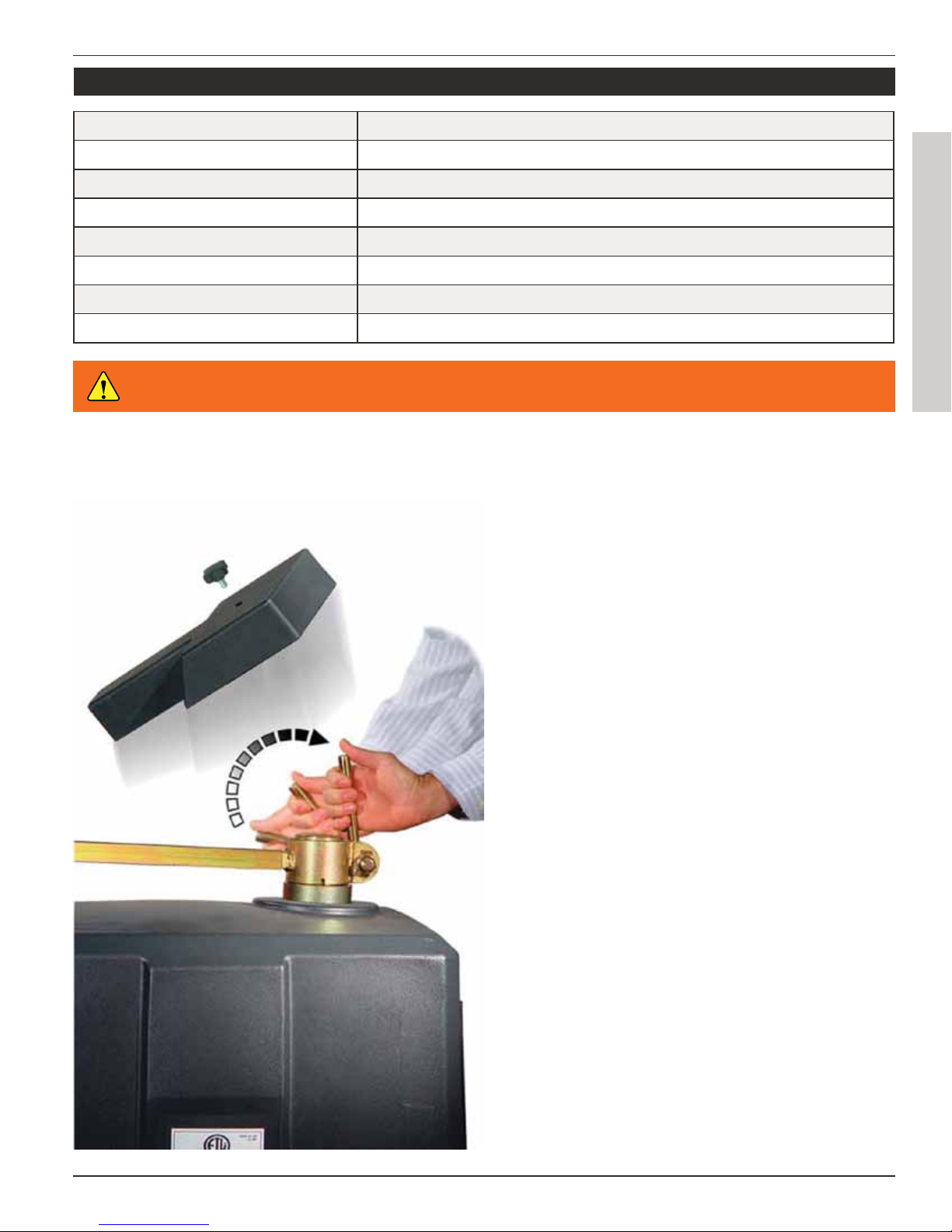
* EMERGENCY RELEASE
By Release Lever; remove cap, lift up emergency re-
lease handle and push gate open.
•Optional BBS. (1000 Lbs Max)
•Optional Power Inverter. ( 3/4 Hp units only)
6
RAM 30-30
RAMSET
www.ramsetinc.com
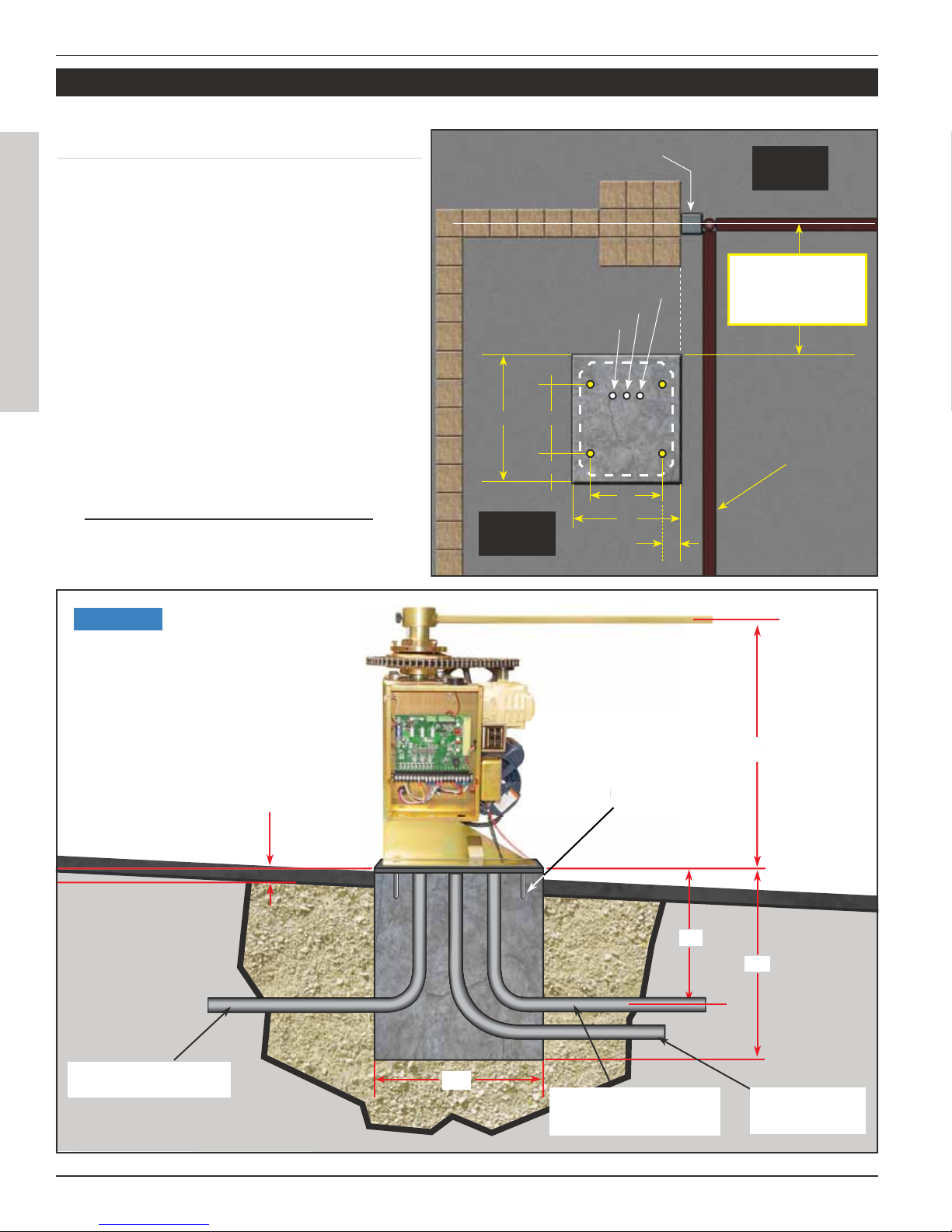
CONCRETE PAD CONSTRUCTION:
Dimensions given for the pad are based on soil
bearing shear of 2000 P.S.F. These figures may
have to be adjusted depending on local soil
conditions.
1. Construct form for mounting pad according
to dimensions shown in Figure 1 and 2.
2. Locate mounting pad according to dimen-
sions given in illustration.
3. Level top edge of form.
4. Set reinforcing bars and wire mesh.
5. Allow pad to cure for 48 hours, and remove
forms.
6. Note: conduits 6” above concrete pad.
INSTALLATION SPECIFICATIONS
GROUND LEVEL
ELECTRICAL
CONDUIT FOR
MASTER/SLAVE
DEDICATED CONDUIT
WITH 15 amp BREAKER
3/4” ANCHOR
BOLTS 4X
INDEPENDENT CONDUIT
FOR LOW VOLTAGE
WIRES
18”
18”
24”
15”
ALLOW 2” ABOVE
GROUND LEVEL
MINIMUM FOR
LEVELING.
3
/4” ANCHOR
BO
LT
S
4
X
15
”
Figure 2
Gate Opened
CONDUIT FOR ELECTRIC POWER
CONDUIT FOR MASTER/SLAVE
CONDUIT FOR COMMUNICATION
Steel Square Tubing
4x4
STANDARD
INSTALLATIONS
Gates From: 8’-16’ (18”)
Gates From 16’-22’ (24”)
Inside
Property
Outside
Property
14”
2 1/2”
20”
6 3/4”
26” 13”

RAM 30-30
7
RAMSET
www.ramsetinc.com
Note: 15 amp wires connected to independent
breaker.
Outlet
Leads
Gate travel is adjusted by loosening the lim-
it Cams and adjusting them until proper gate
travel has been achieved.
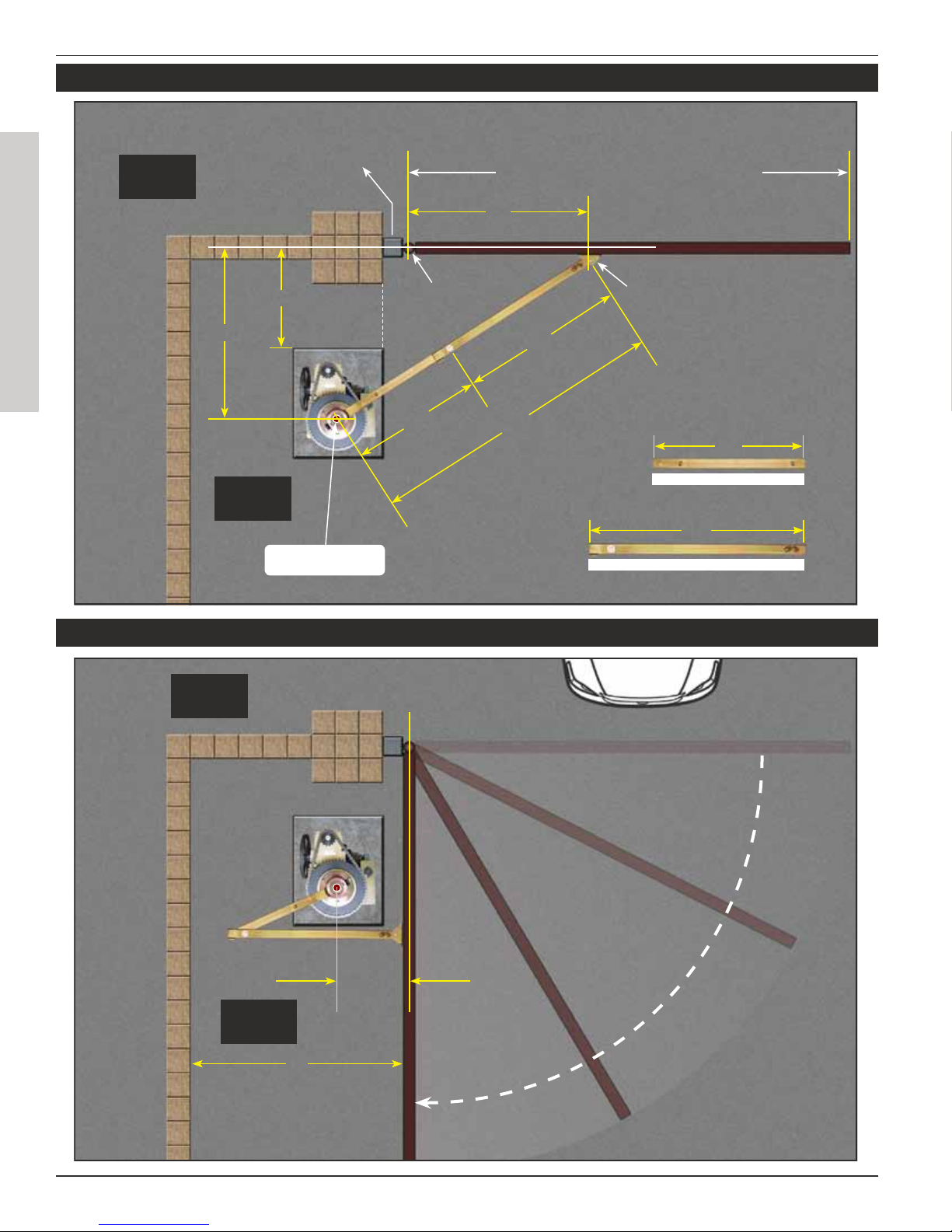
STANDARD INSTALLATION FOR GATES FROM 8’ TO 16’ IN LENGTH
HOOKUP ELECTRICAL POWER GATE TRAVEL ADJUSTMENT
Figure 4
WARNING Do not exceed the specifications. The warranty on your unit will be void if the
installation exceeds the recommended specifications.
Steel Square Tubing
4x4
Supplied Bracket
Gate Rotation
Center (Hinge)
44”
8’ to 16’ Maximum Gate Length
Gate Closed
39”
68”
28” 38”
29”
SHORT ARM DIM. LONG ARM DIM.
36”
18”
Inside
Property
OPERATOR
PIVOT SHAFT CENTER
Outside
Property
8
RAM 30-30
RAMSET
www.ramsetinc.com
STANDARD INSTALLATION FOR GATES FROM 16’ TO 20’ IN LENGTH
SPACE REQUIRED FOR A STANDARD GATE IN THE OPEN POSITION
4’ Gate Opened
15 1/4”
Inside
Property
Outside
Property
4 ft. Length is the minimum
space required between
the open gate to the wall
for this standard installation.
Steel Square Tubing
4x4
Supplied Bracket
Gate Rotation
Center (Hinge)
16’ to 20’ Maximum Gate Length
Gate Closed
43 1/4”
33 1/4” 76 1/2”
42”
SHORT ARM DIM.
LONG ARM DIM.
42”
24”
Inside
Property
OPERATOR
PIVOT SHAFT CENTER
Outside
Property
32”
50”
Table of contents
Other RAMSET Gate Opener manuals

RAMSET
RAMSET RAM 3000 UL User manual

RAMSET
RAMSET RAM 30 User manual

RAMSET
RAMSET RAM 100 User manual

RAMSET
RAMSET RAM-5500 UL User manual

RAMSET
RAMSET RAM 300 UL User manual

RAMSET
RAMSET ALL SECURE User manual

RAMSET
RAMSET RAM 5500 User manual

RAMSET
RAMSET JET User manual

RAMSET
RAMSET RAM-30 UL User manual

RAMSET
RAMSET RAM 300 User manual