quiko HYDRO H300BAC User manual

battenti
I
T
A
L
I
A
N
O
HYDRAULIC OPERATOR FOR SWING GATES
u
s
e
a
n
d
m
a
i
n
t
e
n
a
n
c
e
m
a
n
u
a
l
HYDRO
E
N
G
L
I
S
H
V07/2017
NEW 2017 MODEL
50/60 Hz
yes
open-closed
yes
open-closed
Hydraulic lock
Slow travel Hydraulic slow down (only closing)
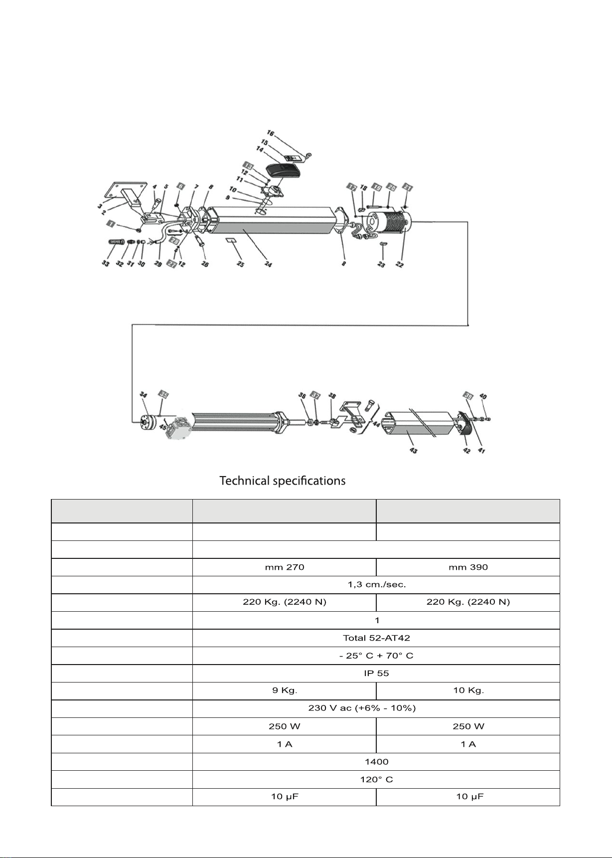
Rod stroke (MAX)
Rod linear speed
Traction / Thrust force to 15 bar
Pump flow-rate (l/m)
Hydraulic oil
Operating ambient
temperature
Protection class
Operator weight
Power supply
Absorbed power
Absorbed current
Electric motor (rpm)
Thermal protection
Capacitor
MODEL
Exploded View
H300BAC H400BAC

1.2. OPERATOR DESCRIPTION
ENGLISH
These instructions apply to the following models:
HYDRO.
The HYDRO hydraulic operator for swing gate, they are constituted by an enbloc composed of an electric pump and a
hidraulic piston that transmits the movement to the the gate.
The HYDRO operator guarantees
mechanical locking of the leaf when the motor is not operating.
The hydraulic operator HYDRO is designed and produced to automate swing gates.
1. DESCRIPTION AND TECHNICAL SPECIFICATIONS
1.1. DIMENSIONS
DIMENSIONS (mm)
LENGTH (A)
Distance attacks (B)
Rod stroke (C)
1) Electric motor
2) Release lock
3) Hydraulic piston
4) Cylinder
5) By-pass valves
6) Pump
7) Electrical power cable
8) Front attack
9) Cover for stroke
10) Kit release
11) Rear attack
12) Rod end
2. ELECTRIC STANDARD DEVICES
1) Hydraulic operators
2) Photocells
3) Electronic control box
4) Key selector
5) Receiver
6) Flashing light
7) Electric lock
You needs always to separate the connecting cables
of the low voltage accessories from the 230 V.
Use separate sheaths to avoid any type of interference.
Connect power cables hydraulic operator:
- Co (Common) = gray cable
- Ap (open) = brown cable
- Ch (closing) = black cable
- T (earth) = yellow / green
3. INSTALLING SYSTEM
3.1. PRELIMINARY CHECKS OF THE GATE
For a correct operating gate must satisfy the following
conditions:
- robust and rigid structure of the leaves;
- the leaf movement should be smooth and uniform but without
any friction during the race;
- the hinges must be in excellent state;
- limit mechanical stops placed.
Any metalwork shall be conducted before installation of
automation.
The state of the gate structure influence the reliability and
safety of the automatism.
H300
H400

Fig. 1
Fig. 2
Fig. 3
Plate
to wall
Plate
attack
ENGLISH
3.2. HYDRAULIC OPERATOR INSTALLATION
A) Attach the rear mounting on the pillar and follow the signs of
Tables A and B, modify, if necessary, the length of the attack
(fig. 1).
Compliance with the dimensions shown in the above tables to
ensure the smooth operation of the automatism.
In the case of an iron pillar carefully weld the rear mounting
directly on the pier.
In the case of masonry opt for one of the following solutions:
1) Cash suitably a plate to wall, and then pay back the attack;
2) Fix to the pillar, with screws and dowel, the rear mounting
plate and weld the rear mounting plate (Fig. 2);
B)Attach the operator to the rear (Fig. 2);
C) Tighten the front end in the middle (rod) on the shaft and
tighten the nut (fig. 3);
D) Release the hydraulic operator; (Fig. 10)
E) Remove the chromed rod to the full bar;
F) Re-lock the hydraulic operator; (Fig. 10)
G) Install the front end on the stroke (Fig. 4);
H) Close the door of the gate and, keeping the operator in
perfectly level position, locate the position of a front on the
wing (Fig. 4);
I) Temporarily fasten the front attachment on the gate by two
spot welds (protect the stroke from any welding slag);
L) Release the hydraulic operator, make sure the gate is open
and free to stay on the mechanical stops to limit pre-installed
and verify that the movement of the gate is smooth and without
friction;
M) Remove the operator from its temporarily and permanently
weld the front attachment on the wing(Fig. 5);
N)Attach the cover rod hydraulic operator (Fig. 7);
O) Re-lock the hydraulic operator and to effectue the electrical
connections with the electronic equipment, according to the
instructions in the manual.
dimensions in mm.
distance attacks (*)
TABLE «A»:H300 - Fixing brackets
TABLE «B»:H400 - Fixing brackets
(*) rod stroke required to stem the slowdown in the closing
(**) max dimensions
hydraulic
In the case that the dimensions of the pilar or the position of the
hinge (dimension D) are not able to contain the dimension A as
it wishes, it is necessary to make a niche on the pillar (Fig. 6),
the dimension A must be always greater than the distance E.
OPENING
ANGLE
OPENING
ANGLE
(*) rod stroke required to stem the slowdown in the closing
(**) max dimensions
hydraulic

Fig. 4
Fig. 5
Fig. 6 Fig. 8
Fig. 7
ENGLISH
3.3. SPECIAL INSTALLING FOR HYDRAULIC OPERATOR
WITH OPENING GATE OUT (Fig. 8)
The mounting dimensions of the hydraulic operator is
detected by the following Table C.
In case of opening gate to the outside, adjust the anti-trap, as
follows:
- Screw A = valve regulation closing force,
- Screw B = valve regulation opening force.
To r educe the torque, you need to turn the screw
counterclockwise;
To increase the torque, you need to turn the screws clockwise.
TABLE «C»:H300 - Fixing brackets
OPENING
ANGLE
(*) rod stroke required without the hydraulic slowdown
(**) max dimensions
Length dimension A=50 mm
Length dimension B=+ 100 mm

4.1. SETTING ANTI-TRAP (fig.9)
4.3. AUTOMATISM TEST
5.2. AUTOMATED SYSTEM RESET
ENGLISH
4. ANTI-CRUSHING CONTROL SYSTEM
- FINAL OPERATIONS - TEST AUTOMATION
The hydraulic operators have a security anti-trap for
to control the hydraulic operator force, in the presence of an
obstacle during the movement of the gate.
The force is adjusted as follows:
- slide to unlock and lift the cap
- lift the base of the release
- to act on the control valves:
1) valve "A" to adjust the opening force
2) valve "B" to adjust the closing force
3) valve "C" to unlock it completely.
Turning the valve clockwise to increase torque, and
counterclockwise to decrease the torque.
The adjustment of the torque limiters,in EU member states,is
subject to standards EN 12445 and EN 12453.
In the other states is subject to local regulations.
4.2. FINAL OPERATION
After the adjusting anti-trap, follow these steps:
- close the device of the release
- remove the vent screw (Fig. 10).
After installation proceed with care to the test for verification
the automation functionality and all the accessories
connected with particular attention to security devices.
Give the "User Guide" to customer and explain the correct use
of the automated system and highlight areas of potential
danger from it.
5. MANUAL OPERATION AND RESET
5.1. MANUAL OPERATION
In case is necessary to manually operate the gate for absence
of electric tide or damage of the automation, you must be acted
on the device of unblocking as it follows:
- to open the cork of coverage unblocking and to insert the
special key in endowment;
- to rotate the key counterclockwise sense for to unlock;
- to effect manually the manoeuvre opening or closing of the
gate.
Before proceeding to the reset of the automated system, after
manual unblocking, it is advisable to disconnect the power
supply of the automatism, with the purpose to avoid that an
unintentional impulse can operate the automation.
The reset operation must be effected as it follows:
- to rotate the key of unblocking counterclockwise sense up to
the arrest;
- to close again the cork of coverage of the unblocking system;
- to insert again the power supply of the automation;
- to start the automation.
6. MAINTENANCE AND REPAIR
6.1. MAINTENANCE
In case of oil topping up must be strictly used Total oil
52-AT42
Periodically check the proper adjustment of the anti-crushing
safety (valve regulating power) and efficiency of the release
system.
The functional verification of the plant is recommended every
six months, with particular attention to the efficiency of the
safety devices and unblocking, included the verification of the
thrust force of the hyfraulic operator; it is also well to verify the
degree of functionality of the hinges of the gate.
Check the level oil inside the oil tank.
6.2. REPAIR
The possible reparations on the automation must be effected
exclusively from specialized personal, possibly authorized.
To use original spare parts.
7. TROUBLESHOOTING
Gate not moving
Gate moving slowly
Gate moving to tears
Oil leakage from the vent screw
Stop leaves at slow down
Rod stroke variable speed
- control power supply
- check that the operator is released
- check adjustment anti-crushing system
- check oil level in the tank
- check efficiency capacitor
- check efficiency of the electronic control unit.
- check adjustment anti-crushing system
- Verify the removal of the bleed screw oil
- to eliminate possible air in the hydraulic circuit,
effecting complete cycles of opening
and closing of the gate
- It is normal for a minimum initial oil leakage,
if theoil leakage is continuing, verify the perfect
horizontal position of the hydraulic operator.
Otherwise, contact an authorized personal.
- check adjustment anti-crushing system
- to verify the quotas of the angle opening
olio
Fig. 9
A
B
apertura
chiusura
Release control valve fully open
Control valve
closing force
Control valve
opening force
Oil distributor
Fig. 10
Oil vent screw

DECLARATION OF CONFORMITY
(OF THE MANUFACTURER)
Manufacturer: QUIKO ITALY SAS
hereby declares, under his liability, that products:
QK-H300BAC
are in compliance with the essential safety requirements of the regulations:
Electro-magnetic Compatibility Directive .........................2004/108/EC
Low Voltage Directive ......................................................2006/95/EC
Machinery Directive .........................................................2006/42/EC
and their amendments and modifications, and with the regulations set forth by the
National Legislative Body of the country in which the machinery is destined for use.
Via Seccalegno, 19
36040 Sossano (VI)
Italia
QK-H400BAC
Managing Directo r
Luca Borinato
Sossano, 19/01/2017

QUIKO ITALY
Via Seccalegno, 19
36040 Sossano (VI) - Italy
Tel. +39 0444 785513
Fax +39 0444 782371
info@quiko.biz
www.quikoitaly.com

battenti
I
T
A
L
I
A
N
O
OPERATORE OLEODINAMICO PER CANCELLI A BATTENTE
HYDRO
V07/2017
NUOVO MODELLO 2017
Manuale
d’installazione
e
d’uso
I
T
A
L
I
A
N
O

ITALIANO
MODELLO
Blocco Idraulico
in apertura
in chiusura
in apertura
in chiusura
Rallentamento corsa Idraulico solo in chiusura
Corsa stelo
(MAX)
mm 270
1,3 cm./sec.
mm 390
Velocità lineare stelo
Forza di spinta / trazione a 15 bar
220 Kg. (2240 N)
Portata pompa (l/m)
Total 52-AT42
1
Olio idraulico
Temperatura ambiente
di esercizio - 25° C + 70° C
Grado di protezione IP 55
9 Kg. 10 Kg.
Peso attuatore
Tensione di alimentazione 230 V ac (+6% - 10%) 50/60Hz
Potenza assorbita 250 W
1400
250 W
Corrente assorbita 1 A 1 A
Motore elettrico (giri/min.)
Termoprotezione motore 120° C
10 µF
Condensatore di spunto 10 µF
Caratteristiche tecniche
QK-H300BAC QK-H400BAC
Vista esplosa
220 Kg. (2240 N)
This manual suits for next models
1
Table of contents
Languages:
Other quiko Gate Opener manuals

quiko
quiko QK-E400 User manual

quiko
quiko Titano QK-T4000 User manual

quiko
quiko Rotello QK-R300 User manual

quiko
quiko NEO Series User manual

quiko
quiko SPIDER QK-S400KIT User manual

quiko
quiko QK-CE24BATR User manual

quiko
quiko QK-H300 Guide

quiko
quiko QK-S400 User manual

quiko
quiko Zebra Series User manual

quiko
quiko SCARABEO QK-SCA230 User manual


