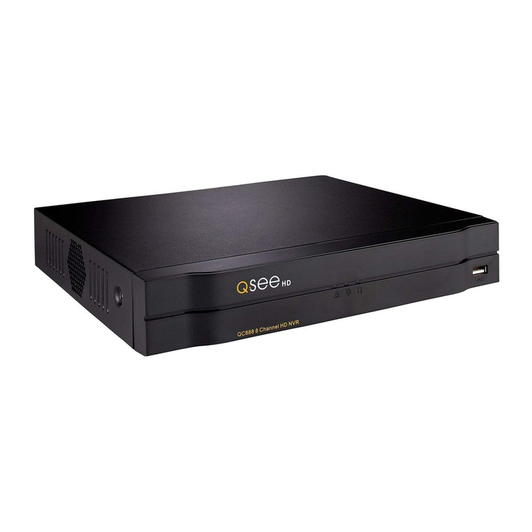
Q-See QSNDVR16M User manual

User’s manual for MPEG4 DVR
Model QSNDVR9M and QSNDVR16M
*This manual is for MPEG4 QSNDVR9M 9-channel and QSNDVR16M 16-channel digital video recorder
And uses the 16-channel digital video recorder as example.
Before operation, we strongly advise that you read the user manual and keep it available for future use.
This manual is an operational guide, we reserve the right to correct typographical errors or inconsistencies with future versions,
software upgrades and product improvements. These changes will be made without any special or advance notification.
Rev 101007
Page 1

Table of Contents
Digital Video Recorder (DVR) Introduction ..................................................................................................... 4
1.1 Product introduction .......................................................................................................................... 4
1.2 Features of this DVR.......................................................................................................................... 4
Installation Notice ......................................................................................................................................... 7
2.1 Checking the Contents………………................................................................................................. 7
2.2 Installing the HDD ........................................................................................................................... 7
2.2.1 Install reminder...................................................................................................................... 7
2.2.2 Install tool ............................................................................................................................... 8
2.2.3 Install process ........................................................................................................................ 8
2.3 Back panel and interface terminals ................................................................................................. 16
2.3.1 Back panel of 16-channel DVR ............................................................................................. 16
2.3.2 Back panel of 9-channel DVR ............................................................................................... 20
2.4 Front panel and interface terminals ................................................................................................. 21
2.5 Remote control description............................................................................................................... 24
2.6 Alarm cable connection ................................................................................................................... 29
Basic operation guide................................................................................................................................... 30
3.1 How to start the DVR....................................................................................................................... 30
3.2 Login and setup the system ............................................................................................................ 32
Page 2

3.2.1 SETUP-SYSTEM .................................................................................................................. 34
3.2.2 SETUP-LIVE ......................................................................................................................... 39
3.2.3 SETUP-REC ......................................................................................................................... 42
3.2.4 SETUP-STORAGE ............................................................................................................... 50
3.2.5 SETUP-NETWORK............................................................................................................... 52
3.2.5.1 MONITORING FROM COMPUTER ON SAME ROUTER................................................. 53
3.2.5.2 MONITORING FROM A REMOTE COMPUTER............................................................... 54
3.2.5.3 PLAYBACK RECORDED FILE.......................................................................................... 56
3.2.6 SETUP-SENSOR/ALARM .................................................................................................... 57
3.2.7 SETUP-AUDIO...................................................................................................................... 61
3.3 Function ................................................................................................................................... 62
3.3.1 STATUS ................................................................................................................................ 62
3.3.2 AUDIO................................................................................................................................... 63
3.3.3 BACKUP & VIEW BACKUP ................................................................................................. 64
3.3.4 PAN/TILT............................................................................................................................... 71
3.3.5 ZOOM/FOCUS...................................................................................................................... 71
3.3.6 SEQUENCE .......................................................................................................................... 72
3.3.7 LOG LIST.............................................................................................................................. 73
3.4 Search record.......................................................................................................................... 75
3.5 SPOT ........................................................................................................................................ 81
Appendix A Main Standard & Parameter chart.................................................................................... 83
Appendix B Recording capability........................................................................................................ 87
Appendix C The meaning of some abbreviations .................................................................................88
Page 3

Digital
Video
Recorder
(DVR)
Introduction
1.1 Product introduction
This DVR is designed specially for CCTV system. It uses an embedded processor and embedded
operating system working with the high-powered code and decode chip. In addition, it uses advanced
IT technology to make the system more stable, such as the audio code and decode technology, large
capacity hard disks, complying with the TCP/IP protocol SoC, etc…
It is a stand alone unit, but also works through the internet to allow the customer to have remote
Surveillance. It is ideal for middle-risk to high risk site surveillance. Due to its good performance it is used in
the Banking Industry, Telecommunication Industry, Electric Power Departments, Legal Systems, Factories,
Wherehouses, Cities, etc…
1.2 Features of this DVR
General
Video output: CVBS, S-VIDEO, VGA and SPOT monitor
Triplex operation: view/record/playback/remote operation at the same time
Various recording resolutions, D1, Half D1 and CIF
Supports channel security by hiding live display
Display the local record state and the basic information
Remote control equipped
Support two level password control: administrator and common user
Operation log recording and searching
Video system (PAL or NTSC) can be detected automatically and selected manually
Recording list can be deleted one by one or all and locked to protect important records
Support water mark technology
Page 4

Format
Standard MPEG-4 compression format
Storage
Supports up to four IDE Hard Drives simultaneously (Or three IDE HDDs and one IDE DVD-RW/CD-RW)
Backup
Auto-play software automatically packed in backup files, and Auto-water-mark check in backup files to
assure files’ authenticity
Support backup via USB 2.0 to USB flash memory, or CDRW, DVD-RW to CD-R/DVD-R respectively
Support remote backup by “Net Client” through LAN or internet
Record and playback
Record modes: Manual, Sensor detection, Timer, Motion detection and Continuous
Support HDD recycle (automatically overwrites older files)
Up to 16CH playback, fast forward 2X 4X 8X 16 32X 64X and 128X and slow forward modes;
play the record frame by frame; jog shuffle to forward/backward function, which is including frame
rate adjusting
Support remote playback in “Net Client” through LAN or internet
Three record search modes: time search, event search, file search
Page 5

Alarm
9/16 alarm inputs and 4 alarm outputs, TTL alarm output
PTZ control
Supports decoder which communicates with RS485
Supports speed dome
Supports PTZ through network
Communication port
RS 485 equipped
Network
Supports TCP/IP protocol
Supports wide bandwidth network through modem (PPPOE)
Supports static IP and dynamic IP (DHCP)
Real time preview/playback/monitoring with audio signal through network
Supports control PTZ camera through the network
Support IE browser, for remote view (automatically download active-x )
Page 6

Installation
Notice
Attention: Before connecting to other equipment, please make sure the device is powered off.
Do not hot plug in!
2.1 Checking the contents
Check the contents when you receive the unit, to make sure you have all the parts. Normally it will
contain: a remote control, a power cable, a CD-Rom with “Net Client” software, screws for installing HDDs
2.2 Installing the Hard Drive
2.2.1 Install reminder
Please confirm the size of HDDs needed and choose suitable ones to install. If the original DVR does not
have HDDs, it is advisable to have professionals install/uninstall the drives.
Page 7

2.2.2 Install tool
One Phillips screwdriver
2.2.3 Install process
Open the DVR using screwdriver
Set one HDD as master and the other as slave if two HDDs are connected to one ATA interface!!!
Attention: Hard Drives connected to the same parallel cable can not be set as master+master or
slave+slave, they must be master+slave!!!
HDD setup: Usinga Maxtor Hard Drive (DiamondMax Plus 8 ATA/133 40GB) as example.
Read the jumper diagram on the rear of HDD
No
jumper=DS(SLAVE)
Page 8


Jumper area
The picture blow is the IDE connection/Power connection section of the HDD.
Jumper according to the diagram above
Jump
er
area
MASTER
SLAVE
The sequence of read/write data from HDD
The ATA interface which is near the motherboard center is the secondary interface, the next ATA
interface which is near the motherboard edge is the primary interface. The sketch is in the following.
The HDD names are shown in the DVR system as HDD A/B/C/D. The master HDD connected to
Page 9
This manual suits for next models
1
Table of contents
Other Q-See DVR manuals

Q-See
Q-See QT5116 User manual

Q-See
Q-See QSD9004 series User guide

Q-See
Q-See Prosumer QT528 User manual

Q-See
Q-See QSD42908C8 User manual

Q-See
Q-See QSDR16RTC/B User manual

Q-See
Q-See QSDR04RTC User manual

Q-See
Q-See QS SERIES User manual

Q-See
Q-See QSD2308C8 User manual

Q-See
Q-See QQTT1199DD332288SSCC User manual

Q-See
Q-See QSD2216C16-250 User manual

Q-See
Q-See QT17DVR4C User manual

Q-See
Q-See QSTD2404 User manual

Q-See
Q-See QSDF8204C4 User manual

Q-See
Q-See QC-SERIES User manual

Q-See
Q-See QT SERIES User manual

Q-See
Q-See QSD9004CM User manual

Q-See
Q-See QT454 User manual

Q-See
Q-See QT848 User manual

Q-See
Q-See QS458 User manual

Q-See
Q-See QSC26408 User manual