
Q-See QR-SERIES User manual

1
H.264 NETWORK DVRs
User Manual
QR-SERIES

2 3
© 2010, 2011 Q-See. Reproduction in whole or in part without written permission is
prohibited. All rights reserved. This manual and software and hardware described herein, in
whole or in part, may not be reproduced, translated, or reduced to any machine-readable
form without prior written approval.
Trademarks: All brand names and products are trademarks or registered trademarks of their
respective owners.
Q-See is a registered trademark of DPS, Inc.
Disclaimer: The information in this document is subject to change without notice. The
manufacturer makes no representations or warranties, either express or implied, of any kind
with respect to completeness of its contents.
Manufacturer shall not be liable for any damages whatsoever from misuse of this product.
Thank You for Choosing a Q-See Product!
All of our products are backed by a conditional service warranty covering all hardware for 12
months from the date of purchase. Additionally, our products also come with a free exchange
policy that covers all manufacturing defects for one month from the date of purchase.
Permanent upgrading service is provided for the software and is available at www.Q-See.com.
Be certain to make the most of your warranty by completing the registration form online. In
addition to warranty and technical support benefits, you’ll receive notifications of product
updates along with free downloadable firmware updates for your DVR. Register today at
www.Q-See.com!
Please see the back of this manual for exclusions.
This manual is written for the QR series of DVRs. Not all features and capabilities are shared
across all models so you may see features described which are not applicable or available on
your machine. In addition you may see screen images that do not exactly match those on your
display.
This manual was accurate at the time it was completed. However, because of our ongoing
effort to constantly improve our products, additional features and functions may have
been added since that time and on-screen displays may change. We encourage you to
visit our website at www.Q-see.com to check for the latest firmware updates and product
announcements.
Throughout the manual we have highlighted warnings and other important information that will
assist you in operating your new system in a safe and trouble-free manner. Please take the
time to read and follow all instructions and pay attention to alerts as shown below:
About this Manual
Rev. 1.1 3/24/2011
WARNING!
CAUTION: Boxes with this icon indicate warnings. To prevent
possible injury or damage to the product, read all warnings before
use.
The remote monitoring functions - including networking, monitoring the DVR over the Internet
and using smart phones - have been compiled in the separate Remote Monitoring Guide
which is included on the disk that accompanied your DVR. It is also available online at our
website, www.Q-See.com and can be found by looking up your product’s model number.

4 5
TABLE OF CONTENTS
TABLE OF CONTENTS
CONTENTS
FOR YOUR SAFETY 7
DVR Features 8
Functions 8
Other Features 8
INSTALLING THE DVR 9
Install the Hard Drive 9
Connect DVR to Cameras 9
Connect DVR to External Monitor 9
Connect Power Supply 9
STARTING THE DVR 10
System Initialization 10
Main Interface Screen 10
Troubleshooting 11
Video Loss 11
Alarm Sounds 11
Change To Full Screen View 11
CONFIGURING THE DVR 12
DVR Menu Overview 12
Pop-up Menu 13
Main Menu 13
Camera Setup 14
Set Camera Name and Position 14
Enable Live Viewing 14
Enable Auto-Sequence 15
Setup Color Hue, Brightness, Contrast and Saturation 15
Record Setup 16
Turn Camera Recording On/Off 16
Select Resolution 16
Quality 16
Audio 17
File Size 17
Customizing Record Mode 17
System Functions 18
Setting The Date/Time 18
Password 19
Video Setup 19
Language 20
Info 20
System Maintenance 20
Device Management 21
HDD Management 21
Set Alarm 23
Motion Detect 25
PTZ Setup 26
OPERATING THE DVR 27
Record 27
Stop Recording 27
PTZ Control 27
General 27
Cruise Setup 28
Search Recordings 29
Backup Recorded Files 30
Playback Software 31
Multimedia Player Menu 32
Video Play Settings 32
Audio Settings 33
SPECIFICATIONS 34
APPENDIX 35
Operation Functions 35
Primary Settings 35
Advanced Settings 35
Network Settings 36
Network Functions 36
Auxiliary Functions 36
Menu Button 36
Basic Settings 36
Setting up Alarm Record Mode 37
TROUBLESHOOTING 38

6 7
SYSTEM CONNECTIONS 39
Q-SEE PRODUCT WARRANTY 40
Questions or Comments? Contact Us 41
FOR YOUR SAFETY
To prevent damage to your Q-See product or injury to yourself or to others, read the
following safety precautions in their entirety before installing or using this equipment.
Keep these safety instructions where all those who use the product will read them.
Use the proper power source. Do not use this product with a power source that applies
more than the specied voltage (100-240V AC).
Never insert anything metallic into the DVR. Inserting anything into the DVR or its case
can be a source of dangerous electric shock.
Do not operate in dusty areas. Avoid placing the DVR in places that are dusty.
Do not expose this product to rain or use near water. If this product accidentally gets
wet, unplug it and contact an authorized dealer immediately.
Keep product surfaces clean and dry. To clean the outside case of the DVR, gently wipe
using a lightly dampened cloth (only use water, do not use solvents).
Do not attempt to remove the DVR cover. If there are any unusual sounds or smells
coming from the DVR, unplug it immediately and contact an authorized dealer or
service center. Warning: Do NOT remove the DVR cover as it may result in severe
electrical shock.
Handle DVR box carefully. If you accidentally drop your DVR on any hard surface, it
may cause a malfunction. If the DVR doesn’t work properly due to physical damage,
contact an authorized dealer for repair or exchange.
Use standard lithium cell battery (pre-installed). The standard lithium cell 3v battery,
located on the motherboard, should be replaced if the time clock resets during a power
outage. Warning! Unplug the DVR before replacing the battery or it may result in severe
electrical shock. Properly dispose of old batteries.
Make sure there is proper air circulation around the unit. This DVR system uses a hard
drive for video storage which generates heat during operation. Do not block air holes
located on the bottom, top, sides and back of the DVR as they are designed to keep the
system cool while running. Install or place this product in an area where there is ample
air circulation.
Provide proper ventilation. This DVR has a built-in fan that properly ventilates the
system. Do not cover or impede this fan.

8 9
INSTALLING THE DVR
INSTALL THE HARD DRIVE
1. Use the provided key to open the DVR’s Hard Disk Drive (HDD) drawer illustration
2. Remove screws and carefully open the top cover of the DVR illustration
3. Firmly connect the DVR’s power cord into its corresponding receptacle on the hard
drive illustration
4. Securely insert the data cable into its matching port on hard drive illustration
5. Carefully replace the top cover of the DVR and re-attach screws
CONNECT DVR TO CAMERAS
1. Connect the camera cable to the Video Input port on the DVR illustration
2. Follow same procedure for each camera
3. To connect a PTZ speed dome to the DVR System, connect the PTZ Camera data
cables to your RS485 A & B ports. Illustration See PAGEXXX for additional PTZ
Camera configuration instructions.
CONNECT DVR TO EXTERNAL MONITOR
Using the included BNC to RCA cable, connect the monitor to the Video Output port of the
DVR illustration
CONNECT POWER SUPPLY
1. Connect cameras’ power supply to outlet(s) illustration
2. Connect DVR power supply to outlet illustration
WARNING!
Caution: Always turn off the DVR’s power before installing or
removing the hard drive!
WARNING!
Caution: Only use the power adapter supplied with your DVR
System. Failure to do so may result in system failure.
DVR FEATURES
FUNCTIONS
Real-Time Monitoring: Supports Real-Time Surveillance via Monitor
Save Files: DVR Saves Real-Time Recording of Image Files to HDD
Backup Files: Supports DVR Backup of Recorded Image Files via USB Flash Drive and Hard
Drive
Playback Files: Supports DVR single CH and Multiple CH Playback of Recorded Files
Network Operation: Supports Remote Surveillance by Multiple Users Simultaneously
Alarm Setting: Supports HDD & video input alarm management and external alarm signal
inputs
Mouse Operation: Support for Faster Menu Navigation.
PTZ Control: Supports PTZ camera operations through RS-485.
OTHER FEATURES
• H.264 Video Compression Format; Supports CIF, D1 and HD1 Resolution
• ADPCM Audio Compression Format
• Windows Graphics Interface
• BNC Video Out Port
• Supports Remote Live Viewing Via 3G Mobile Networks
• Email Notification Alerts when Motion is Detected by System
• Triplex Technology allows for Simultaneous Recording, Playback and
Internet Transmission
• Supports USB Mouse and IR Remote Control Operation
• Rear USB 2.0 Ports For Back-Up, Upgrade and Mouse Operation
• Supports Double Encoded Bit Network Transmission
• Adjustable Video Package Time
• Multiple Alarm Record Mode
• Multiple Language OSD (On Screen Display)
• Supports Auto Maintenance

10 11
SYSTEM INITIALIZATION
1. After connecting the power adapter, turn on the power button
2. The system will boot-up and launch a “System Initializing” message, as shown in
IMAGE 1.
IMAGE 1 IMAGE 2
MAIN INTERFACE SCREEN
Once the system initialization process is complete, the system will enter the main interface
screen (as shown in IMAGE 2).
STARTING THE DVR TROUBLESHOOTING
Video Loss:
If the system does not detect a video input, you will receive a “Video Loss” message for each
camera as depicted in IMAGE 3. Once the cameras have been connected, the Main Interface
screen will display a live feed from each camera in its respective box as shown in IMAGE 2.
Alarm Sounds:
If the first box on the Main Interface screen displays an “H” and an alarm sounds, the DVR
does not detect a HDD. To turn the alarm off, navigate to [Device Management, Alarm setting].
Choose the “off” option next to “HDD loss, HDD space not enough and alarm output”. Return
to the section on installing the DVR and ensure the HDD is installed correctly.
CHANGE TO FULL SCREEN VIEW
To change to a full screen view on one of the cameras, from the Main Interface screen, posi-
tion the mouse over an image and double-click, as shown in IMAGE 4.
Double-click again to return to the multi-camera view (IMAGE 3).
IMAGE 3 IMAGE 4

12 13
POP-UP MENU
The pop-up menu provides access to the Main Menu, Video Search, PTZ, Start Record,
Stop Record, Start Cruise, Start Auto Sequence, and Picture in Picture Mode options.
To display the pop-up menu, as shown in IMAGE 5: From the MAIN INTERFACE screen,
right-click the mouse
To exit the pop-up menu and return to the MAIN INTERFACE screen, click on any area outside
of the pop-up menu
IMAGE 5 IMAGE 6
MAIN MENU
The Main Menu provides access to create management permissions, configure devices, cus-
tomize recording parameters, and set system functions (such as time, date and passwords).
The Main Menu also allows access to controls for the camera, network, HDD, alarm, PTZ, and
mobile phone.
To access the Main Menu (IMAGE 6) from the MAIN INTERFACE screen, right-click using the
mouse or select the Menu button on the front panel of the DVR.
To navigate within the Main Menu:
DRAG AND CLICK MOUSE
USE FWD AND REW BUTTONS ON DVR
USE FWD AND REW BUTTONS ON REMOTE
To return to the previous window within the Main Menu interface:
OPTION, RIGHT-CLICK “EXIT” WITH MOUSE
SELECT ESC BUTTON ON DVR
CONFIGURING THE DVR
CAMERA
COLOR SET
DWELL TIME DISPLAY
SEARCH
PLAYBACK
LIST FILE BACK-UP
HDD MANAGEMENT
ALARM SETTING
PTZ SETTING
AREA SETTING
MOBILE
MOTION
EMAIL
TIME SETTING
USER PASSWORD
AUDIO/VIDEO SETTING
LANGUAGE SELECT
SYSTEM INFORMATION
SYSTEM MAINTENANCE
RECORD
NETWORK
SEARCH
DEVICES
MAIN MENU
SYSTEM
DVR MENU OVERVIEW

14 15
Enable Auto-Sequence
To set the system to automatically rotate the screen view image for each camera:
1. From the camera setup interface, select the AUTOSEQ button
2. The AUTO ROTATION sub menu will appear (IMAGE 8)
3. Select the amount of view time, from 0 to 10 seconds, for each camera from
the drop-down list.
4. To set the rotation time for all cameras to 5 seconds, select DEFAULT.
5. When finished selecting times, select APPLY and then EXIT to close the AUTO
ROTATION menu
Note: changes will only be saved, when you select APPLY before exiting
IMAGE 9
Setup Color Hue, Brightness, Contrast and Saturation
To adjust the image brightness, saturation, contrast and hue settings for each camera, from
the camera setup interface:
1. Under the COLOR column, select the SETUP button
2. The COLOR SETUP sub menu will appear (IMAGE 9)
3. Make desired changes by sliding the vertical line along each axis
4. Select DEFAULT to reset all values to the original factory installed settings
5. To close the window without applying changes, select EXIT, before selecting APPLY
6. To save changes, select APPLY
7. A prompt will appear to save your settings, select OK in order for the changes to take effect.
Note: changes will only be saved, when you select APPLY before exiting
CAMERA SETUP
Set Camera Name and Position
To set up the display name and position for each camera, complete the following instructions:
1. From the Main Menu, select the camera icon
2. From the camera setup interface (IMAGE 7), assign a name for each of camera, up to 8
characters long by highlighting the field next to the channel under the NAME column.
To enter letters, left click the mouse in the field to access the keyboard drop down.
3. To select the camera’s position on the screen, select the arrow under the POSITION
column and select preference
4. Complete steps 2 and 3, for each camera
5. Click APPLY, then EXIT
Enable Live Viewing
From the camera setup interface (IMAGE 7), enable live viewing for each camera.
1. From the Main Menu, select the camera icon
2. From the camera setup interface (IMAGE 7), select the arrow under the LIVE column
and select preference from the drop down menu
3. Complete step 2, for each camera
IMAGE 7 IMAGE 8

16 17
Audio
Select enable or disable to turn the audio input on or off. When the audio is turned off,
the DVR system will not record audio and you will not hear sound during playback of your
recorded events.
File Size
Select the FILE SIZE drop-down list to set the maximum recording time for all recorded files to
be 15, 30, 45 or 60 minutes in length
Customizing Record Mode
Select the REC MODE drop-down list and choose to record 24 hours a day, on a set schedule
or when motion is detected.
1. To record 24 hours a day, choose the ALWAYS option.
2. To record on motion or a set schedule, select Time Schedule Record and select the
“Schedule” option and the SCHEDULE interface will open (IMAGE 11)
Note: For detailed motion detection setup, please read: “Device Management / Motion Detection”
3. Choose from the channel drop-down menu to adjust the recording options for all
cameras
4. Or to set the recording parameters for each camera separately choose each camera
from the drop down menu
5. To set up the recording by day use the drop down menus labeled “From” and “To” and
select times
6. Selecting the ALARM (motion record), GENERAL (always record) and NO RECORD
boxes allows further customization for each recording time and day
7. The Default recording schedule is as follows:
HR 01:00 AM - 07:59 AM: NOT RECORDING
HR 08:00 AM - 18:59 PM: NORMAL RECORDING
HR 19:00 PM - 00:59 PM: ALARM RECORDING (RECORD ON ACTIVITY OR ALARM ONLY)
8. To close the window without applying changes, select EXIT, before selecting APPLY
9. To save changes, select APPLY
10. A prompt will appear to save your settings, select OK in order for the changes to
take effect.
Note: changes will only be saved, when you select APPLY before exiting
RECORD SETUP
From the Record Setup menu turn the recording status for each camera channel on and off,
set the recorded image quality, enable audio recording, schedule recording times and set
recording file sizes.
To set up the recording options on DVR
1. From the Main Interface screen, go to the Main Menu
2. Select the RECORD icon to open the RECORD SETUP menu (IMAGE 10)
3. Select desired preferences or select DEFAULT to reset all values to the original factory
installed settings
4. To close the window without applying changes, select EXIT, before selecting APPLY
5. To save changes, select APPLY
6. A prompt will appear to save your settings, select OK in order for the changes to take
effect.
Note: changes will only be saved, when you select APPLY before exiting
IMAGE 10 IMAGE 11
Turn Camera Recording On/Off
Select the arrow next to each camera from the top row labeled CHANNEL
Turn each camera to either ON or OFF
Select Resolution
Select D1, HD1 or CIF resolution option for each camera
Quality
Choose the quality of the recorded images for each camera (Best Good or Normal)

18 19
SYSTEM FUNCTIONS
The System Setup menu (IMAGE 25) provides access to configure the following system
settings: Date/Time, Password, Audio/Video, Language, System Info and System
Maintenance.
IMAGE 25 IMAGE 26
Setting The Date/Time
1. From the Main Menu, select SYSTEM to open the SYSTEM SETUP menu
2. Select DATE/TIME to open the TIME SETUP menu (IMAGE 26)
3. Enter the date and select the date format
4. Enter the time and select the time format
5. Select the time zone format (see IMAGE 27 for assistance in selecting the correct time zone)
6. Enable daylight savings time if applicable
7. Select DEFAULT to reset all values to the original factory installed settings
8. Select APPLY to save settings
9. Select EXIT to return to SYSTEM SETUP menu
*Note: The correct time zone must be selected from the Time Zone drop-down menu or the time
management software will not run properly. Follow the time zones as indicated on IMAGE 27. If necessary,
more information about time zones can be found at www.time.gov.
IMAGE 27
Password
The Password Setup dialog box allows the user to enable or disable password protection and
set up an administrator password.
1. From the Main Menu, select SYSTEM to open the SYSTEM SETUP menu
2. Select PASSWORD to open the PASSWORD SETUP menu (IMAGE 28)
3. Change PASSWORD ENABLE setting to ON
4. Enter USER PASSWORD (up to 6 characters)
5. Enter ADMIN PASSWORD (up to 6 characters)
6. Select APPLY to save settings
7. Select EXIT to return to the SYSTEM SETUP menu
IMAGE 28 IMAGE 29
Video Setup
The Video Setup dialogue box allows the user to set the VGA resolution and PAL/NTSC
designation.
1. From the Main Menu, select SYSTEM to open the SYSTEM SETUP menu
2. Select VIDEO to open the VIDEO SETUP menu (IMAGE 29)
3. Select NTSC from the VIDEO SYSTEM drop down menu (NTSC is the standard in the USA)
4. Select APPLY to save settings
5. Select EXIT to return to the SYSTEM SETUP menu
This manual suits for next models
1
Table of contents
Other Q-See DVR manuals

Q-See
Q-See QS434 User manual

Q-See
Q-See QC308 User manual

Q-See
Q-See QS434 User manual

Q-See
Q-See QC444 User manual

Q-See
Q-See QS206 User manual
Q-See
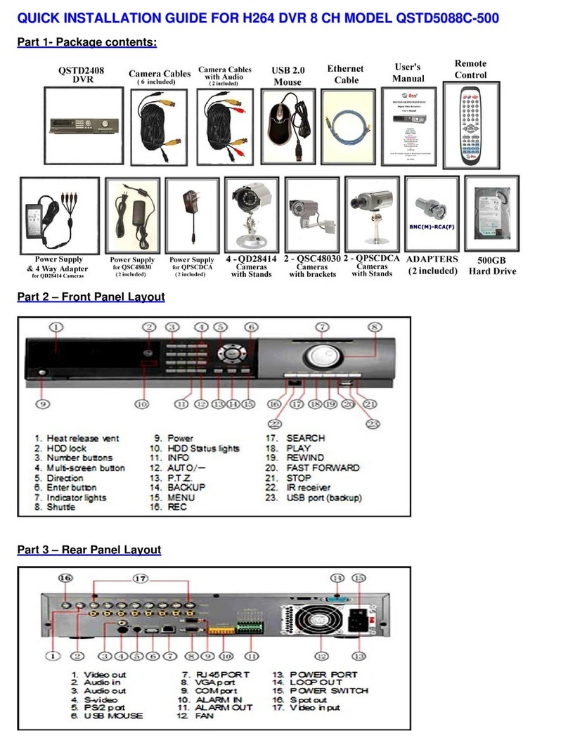
Q-See QSTD2408 User manual

Q-See
Q-See QC3016-12E4-1 User manual

Q-See
Q-See QT428-833 User manual

Q-See
Q-See QSDR44KRTC-320 User manual

Q-See
Q-See QC444-403 User manual

Q-See
Q-See QSC26404 QH32DVR4C User manual

Q-See
Q-See QT SERIES User manual

Q-See
Q-See QS SERIES User manual

Q-See
Q-See QSD9004CM User manual

Q-See
Q-See QSNDVR4R User manual

Q-See
Q-See QSD2014 User manual

Q-See
Q-See QSD2316L User manual

Q-See
Q-See QSD2308C8-250 User manual
Q-See
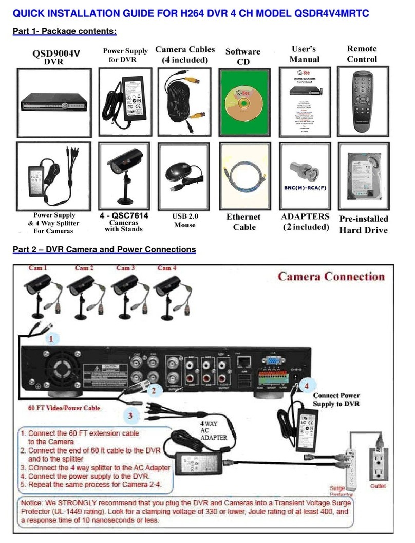
Q-See QSDR4V4MRTC User manual

Q-See
Q-See QSD2316L User guide


