Purivox Carousel Triplex V User manual

Purivox
Carousel
Triplex V
Instruction
manual
1
Hazard warning -
Purivox Carousel Triplex V
Please read the instruction
manual very carefully before using
and assembling the unit.
Using the device indoors is not permitted.
Never point the sound tube in the direction of people or
flammable objects, because a small jet flame and a pressure
wave will exit the sound tube.
Note regulations in terms of storage, setting up and arranging
the propane gas bottle.
The Purivox Carousel Triplex V is only built for using in the
agricultural sector (Proper use)
Any other use is considered improper.
For damage resulting from improper use. The manufacturer of
the equipment shall not be liable.
The Purivox Carousel Triplex V may only be used, maintained
and repaired by persons over 18 years, who are acquainted with
the equipment and informed of risks.
The relevant accident prevention regulations as well as other
generally recognized safety, health rules and regulations must
be observed.
Any modifications to the equipment shall immediately exclude
the manufacturer from any liability or resulting damages.

2
Contents
1 Hazard warning
2 Contents
3 Components - Purivox Carousel Triplex V
4 Electronic unit
5 Power supply / Batteries
6 Timer
7 Shot frequency
8 Volume
9 Number of shots
10 Assembly instruction
22 Spare parts - Electronic unit
23 Spare parts - Purivox Carousel Triplex V
24 Troubleshooting
25 Optional equipment - Mirror pyramid
Notice:
The gas regulator which is shown on all the pictures in the manual is
a German gas regulator type. If you have ordered a unit with a POL
gas regulator, the German regulator is replaced with a POL regulator.
Also the gas bottle can look different to the model that you are using.
But always remember to use only certified propane gas bottles.
3
Components - Purivox Carousel Triplex V
1. Sound tube (106040) 2. Foot plate big (102273)
3. Foot plate small (102275) 4. POL gas regulator complete (101660)
5. Cain 2m (102080) 6. Adjustable pole (102026 & 102028)
7. Pole long (102025) 8. Pole short (102023)
9. Tripod bearing block (102072) 10. Cross bar (102090)
11. Electronic unit (108510)
11
9
8
7
6
5
4
3
2
1
10
4
Gh-1
Gh-2
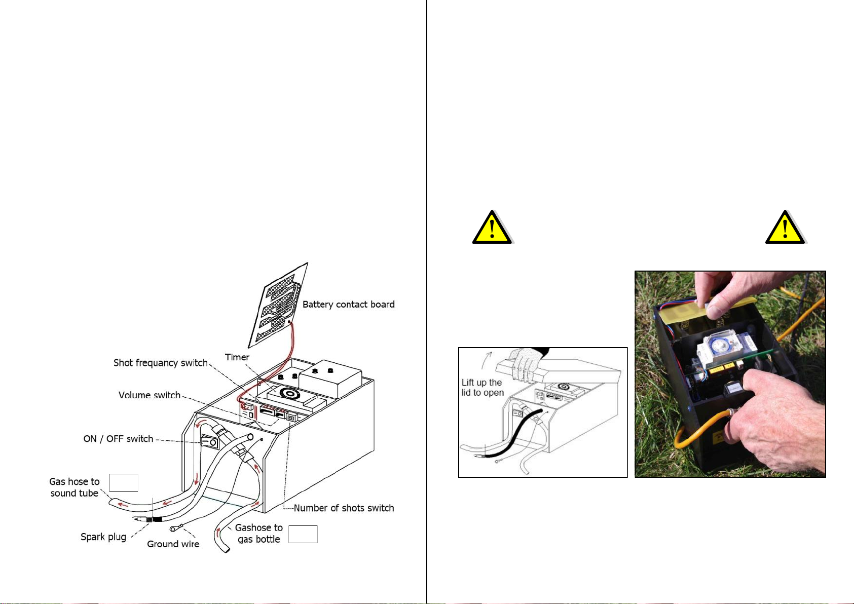
Electronic unit
The controller is in a black weatherproof plastic case.
To get to the operating elements and set up the unit, lift up the lid
Inside of the Electronic unit:
Battery compartment
24 hour Timer
Switch for shot frequency
Switch for volume
Switch for number of shots
Outside of the Electronic unit:
ON / OFF switch
Ignition cable with spark plug and ground wire
Solenoid valve with gas hoses
Gas hoses (Gh-1 and Gh-2)
5
Power supply / Batteries
Before working on the batteries or inserting new batteries,
make sure that the unit is turned OFF!
The ON / OFF switch is on the front of the electronic unit
and is labelled with I for ON and 0 for OFF.
To insert the batteries release the locking by pressing the plastic
plate direction the clock. The battery contact board
can then be removed upwards.
Important:
The batteries must be removed
when the unit is stored!
Open the lid of the electronic unit (108511) and make sure that the paper strip
between the batteries and the contact board is removed.
After this press the battery contact board back down to close it.

6
Setting the timer
If the batteries are inserted and are in contact with the battery contact
board the timer will directly start working
To set up the timer, open the clear cover from the timer.
Setting the actual time
By turning the inner disk clockwise the current time is set to the small arrow.
One turn means one hour.
The little mark on the disc is meant to be the minutes. If the mark shows up it
is one hour, to the right 1/4 hour, downwards 1/2 hour and to
the left a 3/4 hour.
Setting the work time
The clock is set from the factory so that it will work 24 hours. All cams are
pushed outward. To set the pause time, the cams have to pushed in.
Each cam stands for 30 minutes
Cam outside / Unit works
Cam inside / Break (Unit doesn’t work)
The working time should adjust to suit the local conditions. It is recommended to
observe the feeding times of the birds/animals and set the timer to suit.
Council regulations may also need to be observed.
Switch I AUTO 0 always in position “Auto”
Important:
NEVER turn the timer anticlockwise!!
7
The best thing is to start with a setup that bangs not so often.
Only when the number of birds and wild animals is getting bigger then
change the switch (for example from 3 to 2) to reduce the pause interval.
Setting the shot frequency
You can choose from 4 different time frames, how long the pause time should be.
The unit will then shoot randomly in that time to avoid habituation effect.
If the number of birds and wild
animals is not large then it is
possible to increase the pause
time. In our experience, an
intensive multi-shot approach
with longer pause intervals is
much better and more effective
than lots of frequent shots.
Switch position Break time
1Break of 2 –4 minutes
2Break of 4 –8 minutes
3Break of 8 –16 minutes
4Break of 16 –32 minutes
8
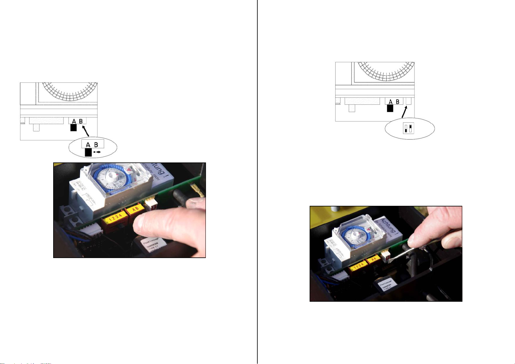
Setting the volume
With a switch on the board the volume of the unit can
be set in two different volumes
For the full volume the switch has to be on position B, for
a reduced volume the switch has to be on A
Switch position A= Reduced sound level
100m distance approx 90db(A)
Switch position B= Full sound level
100m distance approx 96db(A)
9
1 shot = both switches up
2 shot = left up / right down
3 shot = left down / right up
4 shot = both switches down
Setting the number of shots
Changing the number of shots only when the unit is turned off!
Wait 15 seconds before turning the unit on again so it can re-set properly.
The recommended number of shots is 3.
Tests have shown that the best results will be made with the 3 shots.
10
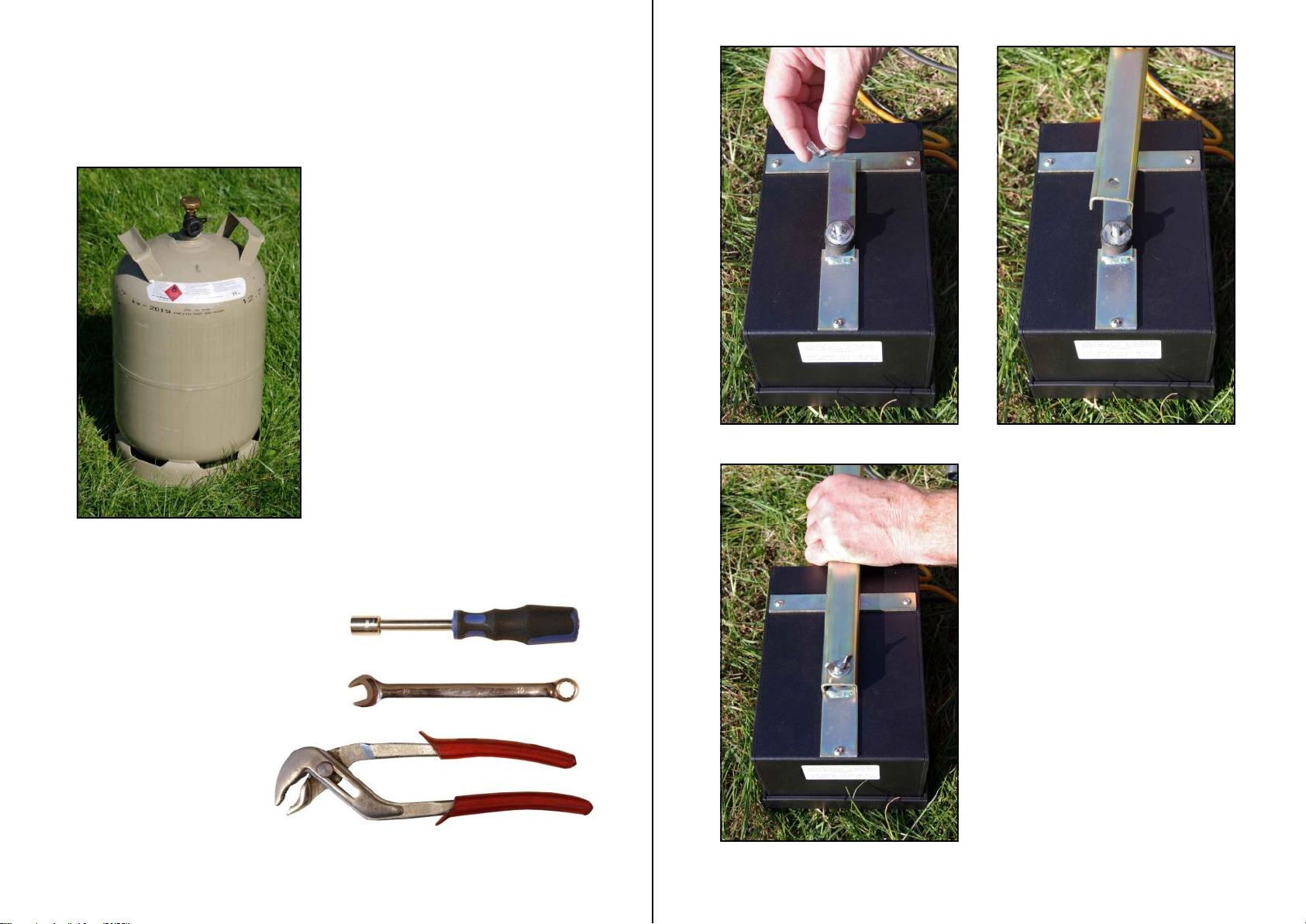
Required tools:
Spanner (size 10) or
socket wrench (size 10)
and
Pliers
A standard propane gas bottle
is required for normal operation.
(Not included in delivery)
Notice:
Propane gas bottle can look similar to
the one which is shown in the manual.
Assembly instruction
Purivox Carousel Triplex V
11
Once the electronic unit is set.
Close the lid of the electronic
unit and turn the electronic unit
over.
Now remove the wing nut, tooth
washer and washer.
Take the cross bar (102090)
and put on end with the hole on
the screw.
Once that is done put the
washer, toothed washer on the
screw and tighten it firmly with
the wing nut.
Use the pliers.
12
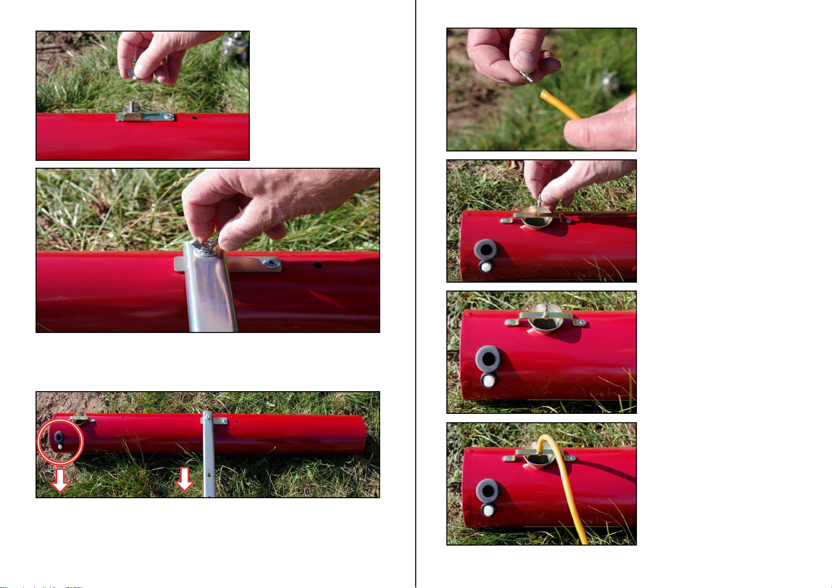
Once this is done the cross bar will be attached to the sound tube
and tightened with the wing nut. Make sure that the cross bar is
Remove the wing nut,
toothed washer and the
washer from the thread on
the sound tube (106040).
Make sure that the opening from the sound tube for the spark plug
shows in the same direction like the cross bar (see picture)
13
Remove the propane nozzle which
is plugged into the gas hose
(Gh-2) which runs away from
the electronic unit.
The propane nozzle will screwed
into the nozzle-bracket from the
sound tube.
Now the gas hose is pushed onto
the gas nozzle. Make sure that it is
the gas hose (Gh-2) which goes
away from the electronic unit.

15
The bearing block (102072) will be screwed on the cross bar and
tighten carefully by using a screwdriver.
14
Unscrew the plastic screw from the thread insert rubber. Take now the plastic
screw; slide it onto the ground wire and through the spark plug.
The spark plug is inserted through the opening of the rubber grommet. Then the
plastic screw is screwed into the thread insert rubber and tightened firmly.
16
Insert the big foot plates (102273) into the
long poles (102025). Make sure to use the long
poles. This will prevent that rainwater can run
into the poles.
Now the short pole (102023) will be fitted to
the long pole.
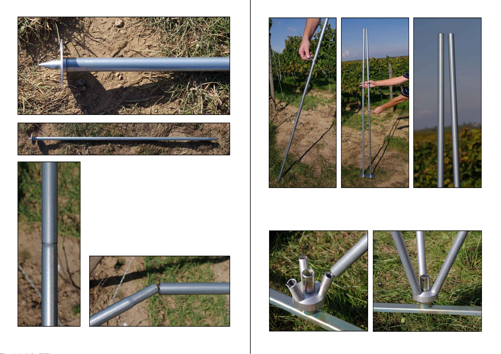
17
Take the adjustable pole (102026 & 102028) and put the small foot
plate (102275) on. Now hold the previously assembled poles (long + short)
next to the adjustable pole. Use the wing screw to adjust the length so
that the adjustable pole has the same length like the other poles.
After this place all three poles on the bearing block.

18
Slide the gas hose (Gh-2) trough
the middle of the bearing block.
Using the adjustable pole the unit
can be adjusted to the ground that
the unit stands horizontally.
After all poles are mounted on the bearing block, the Purivox
Carousel Triplex V can be turned over and put on the foot plates.
19
Hang one side of the chain (102080) with the sharp end of the hook
pointing out of the bearing block. Move the chain
through the handle of the bottle and attach the other end of the chain
also to the bearing block (sharp end outside!)
Table of contents
Other Purivox Farm Equipment manuals


