Prowise iPro Wall Lift User manual

Prowise iPro Wall Lift
Assembly Guide
www.prowise.com PW.1.21002.0002© Prowise 2018

www.prowise.com2
Prowise iPro Wall Lift

NL
DE
EN
Prowise iPro Wall Lift
www.prowise.com3
Table of Contents
Guidelines for the installation of the iPro Wall Lift 4
Scope of delivery 5
Necessary tools 6
Installation of the Prowise iPro Wall Lift 6
Installation of a touchscreen on the Prowise iPro Wall Lift 8
Initialising the lift 10
Lift usage 10

www.prowise.com4
Prowise iPro Wall Lift
Guidelines for the installation of the iPro Wall Lift
Only Prowise or a partner certied by Prowise is authorised to install and mount the touchscreen on the Prowise
iPro Wall Lift. Prowise is not liable for damages and/or trauma caused by assembly carried out by a third party.
The warranty will lapse if the lift or the touchscreen are installed or assembled by third parties.
• The wall must be able to bear twice the weight of the touchscreen. You can nd the weight of the screens on
the website: https://www.prowise.com/en/touchscreens/line-up.
• The maximum load of the Prowise iPro Wall Lift is 110 kg.
• Ensure the wall is free of obstacles (for instance: old blackboards, whiteboards, cupboards, tables or
obstructing installation facilities like heating or electricity tubes).
• The power outlet and the potential UTP socket must be located within 2 meters of the lift, but cannot
obstruct free movement of the lift.
• The power supply must have an available current of 6A.
• Connect the power cord to a grounded socket with AC 100-240V~50/60Hz only. Consult your energy
company if you are unsure about the electricity provision at the place of installation.
• Use only the connection cord and plug supplied.
• Read the safety instructions before assembling the Prowise iPro Wall Lift.
CAUTION! In case a cable tray is running along the wall, an extension kit (PW.2.210002.0003) can be used to
suspend the iPro Wall Lift 75 mm from the wall. Under no circumstance can the cable tray be located between
0-10 cm and 55-65 cm from the oor, because it will obstruct the mounting of the wall brackets.
100
400
200
1250
175 175500

NL
DE
EN
Prowise iPro Wall Lift
www.prowise.com5
Scope of delivery
Check the delivery for completeness. Should component parts be missing, please contact our service desk within
ve (5) days. The contact information for our service desk can be found on our website, www.prowise.com.
Please keep your serial number and a copy of the invoice readily available.
1. Prowise iPro Wall Lift
2. AC connection cable
3. VESA clamps (2 units)
4. Assemblage bag:
a. M8x20 hex bolts (4 units)
b. M5x12 hex bolts (2 units)
c. Assembly Guide
d. Safety Guide
e. Cap Unicap (6 units)
f. Ring Unicap (6 units)
5. AC extension cord for
touchscreen
1
3
2
5
4a 4e
4f
4b
4c
4d

www.prowise.com6
Prowise iPro Wall Lift
Installation of the Prowise iPro Wall Lift
1. Remove the base cover. (Tekening)
a. Remove the foot control panel by
unclicking it.
b. Remove the two hex bolts M5x12
(3 mm hex key).
c. Remove the base cover from the
base manually.
2. Plug the supplied power cord into the
lift and connect to a grounded socket.
3. Put the lift 300 mm up by pressing
the up (+) button on the foot control
panel.
4. Remove the right cable tray by
unscrewing the hex bolts M6x20 (4
mm hex key). Disconnect the left
cable tray and lower it to easily reach
the wall mount.
5. Loosen the wall clamp slightly by
unscrewing the hex bolts M6x6 (4 mm
hex key) a few strokes. (Tekening)
Necessary tools (not included)
• 3 mm, 4 mm and 5 mm hex keys
5
4

NL
DE
EN
Prowise iPro Wall Lift
www.prowise.com7
6. Position the lift against the wall and
ensure it is level.
7. Draw the anchor points on the wall.
8. Disconnect the power cord from the
socket and remove the lift from the
wall.
9. Drill the holes in the designated spots
to mount the lift.
10. Place the lift back in position.
11. Assemble the lift to the wall with
suitable screws/plugs.
12. Set the lift perpendicular and x the
wall clamp to the pillars by tightening
the hex bolts M6x6 (4 mm hex key).
13. Put the cable trays back with the hex
bolts M6x20 (4 mm hex key).
14. Reconnect the power cord to a
grounded socket.
15. Place the casing back over the lift in
reverse order (see point 1). The power
cord can be fed upwards both to the
left and the right of the base cover.

www.prowise.com8
Prowise iPro Wall Lift
Installation of a touchscreen on the
Prowise iPro Wall Lift
1. Mount the VESA brackets to the
touchscreen with the four M8x20 hex
bolts supplied (5 mm hex key).
2. Place the touchscreen with the VESA
brackets on top of the VESA box of
the lift. Ensure that the touchscreen is
properly positioned on the VESA box.

NL
DE
EN
Prowise iPro Wall Lift
www.prowise.com9
4. Plug the lift connection cord into the
touchscreen AC-IN.
5. Connect the lift to the screen by using
the lift USB cable (UART), in order to
control the lift via the touchscreen.
Connect the cable to the USB port
of the Prowise touchscreen, named
‘USB2.0’ (LIFT/SERVICE). Depending
on the screen type, this port can be
found at the bottom of the screen
(left-hand side) or at the bottom (in
the middle) of the screen.
3. Secure the touchscreen with the two
M5x12 hex bolts supplied (3 mm hex
key). Ensure that the touchscreen has
been mounted to the lift correctly.
6. Follow the ‘Initialise lift’ procedure to
align the lift columns.
www.prowise.com10
Prowise iPro Wall Lift
Initialising the lift
Lift usage
• Place the lift in the lowest position by pressing the down button of the foot control panel.
• Once in the lowest position, again press the down button and continue to hold the button until the lift has
moved automatically a further 3 mm and then withdrawn.
• Release the down button only when the lift has come to a complete standstill.
• If the down button is released before the lift has stopped, initialisation will be interrupted and the process
must be restarted.
• The columns are now initialised and ready for use.
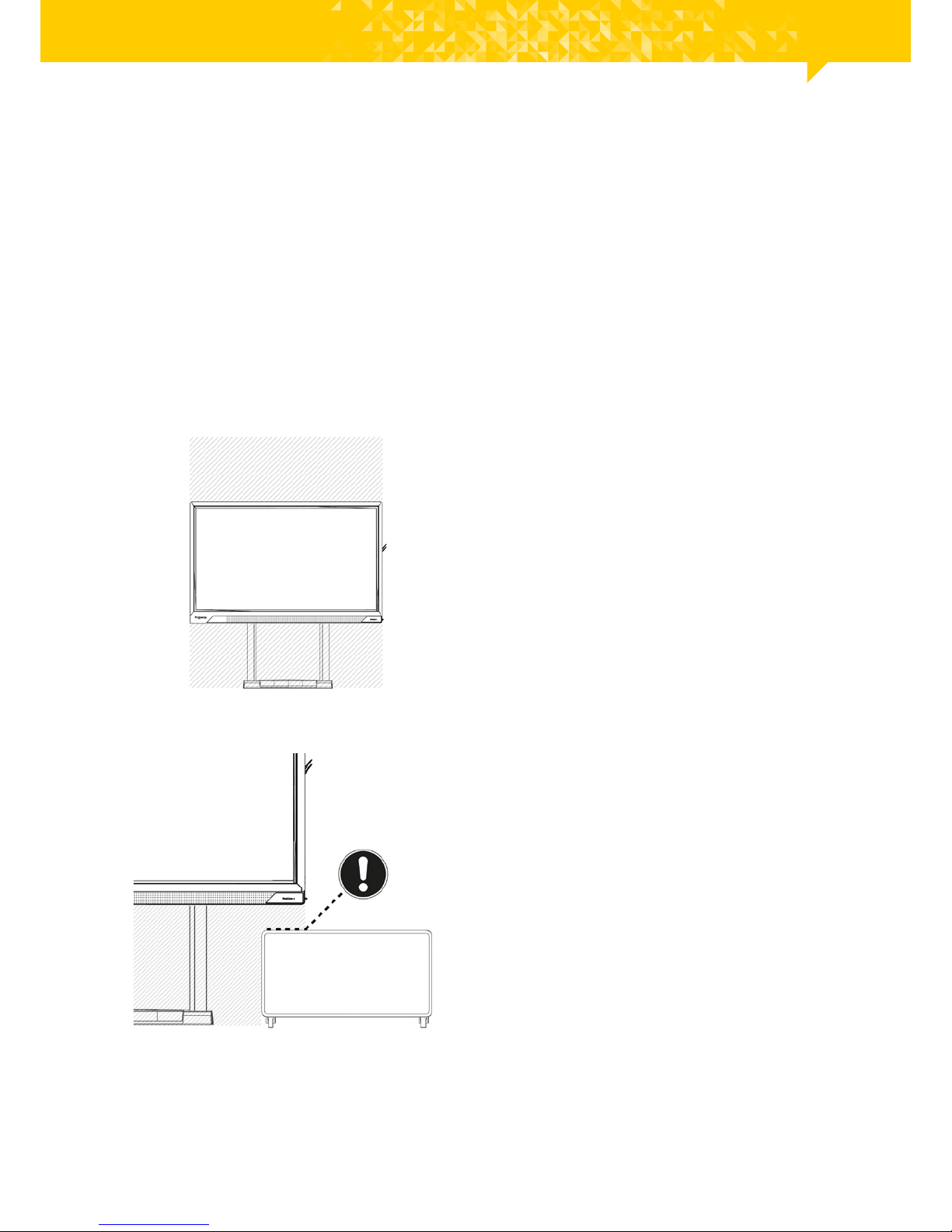
1. The motion area must be free of
obstacles. Ensure that objects or body
part cannot get trapped between
another object and the lift or the
touchscreen.
2. The lift is equipped with anti-collision
sensors that automatically stop it
from moving once it is in collision with
an obstruction. This prevents damage
to the lift and the touchscreen
mounted upon it.
CAUTION! This is not a person protection feature.
Other manuals for iPro Wall Lift
2
Table of contents
Languages:
Popular Rack & Stand manuals by other brands

Salamander
Salamander Acadia AC/W/L400/WH Assembly instructions

Fohhn
Fohhn VAT-09 Mounting instruction

ricoo
ricoo FS0522 quick start guide

AMSOIL
AMSOIL BMK-22 Installation and service instructions

Kargo Master
Kargo Master 48220 installation guide

Milestone AV Technologies
Milestone AV Technologies SIMPLICITY SLF2 installation instructions


