Safety precautions
This radio control is not a toy. Therefore it is not suitable for children under the age of 8. Children under 14
should only operate the remote control system under supervision of an adult.
The radio controlled model is also not a toy. For this reason, you must observe the special safety instructions
of the model manufacturer when installing and using the recever unit.
If you are not familiar with RC models, please contact an experienced model pilot or a model construction
club.
Please check the functional safety of your model and the remote control unit before putting the device in
operation. When doing so, make sure there is no visible damage, such a defective plug connection or dama-
ged cables. All moveable parts of the model must run smoothly, but must not have any play in their bearings.
When the antenna is pressed in, the device should still work wthin a range of approx. 25>30 meters.
Do not expose the transmitter to direct sunlight or excessive heat for an extended period of time.
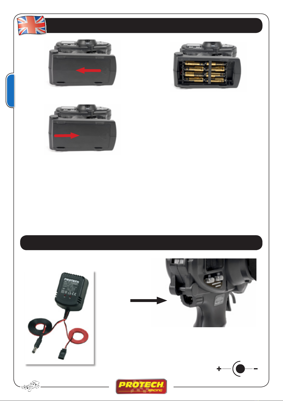
If the battery voltage become too low (alarm), you must immediately change the batteries or recharge the
NiCd batteries to avoid reduction of range control and lost control of the model.
Specifications
Power requirement: 9,0V ~ 12.01V DC
Current drain: 250mA max.
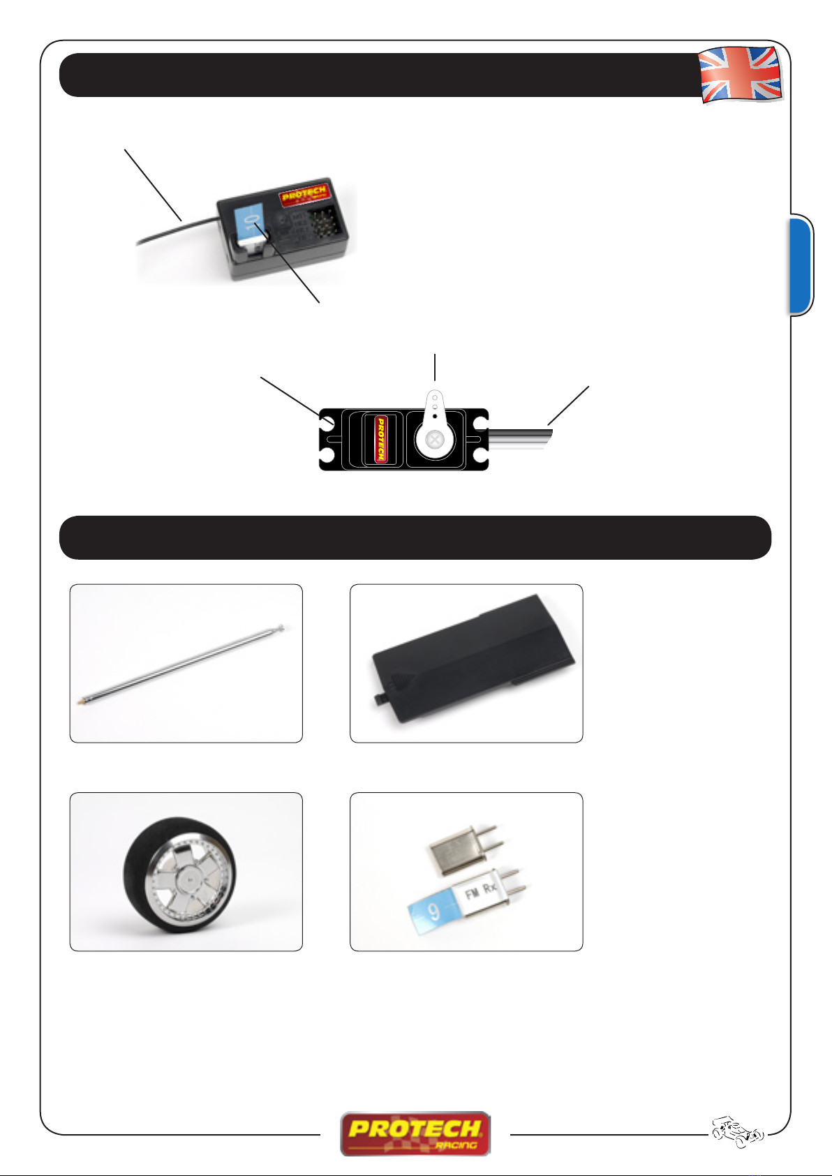
Modulation: FM
Working temperature: 0°C ~ 70°C
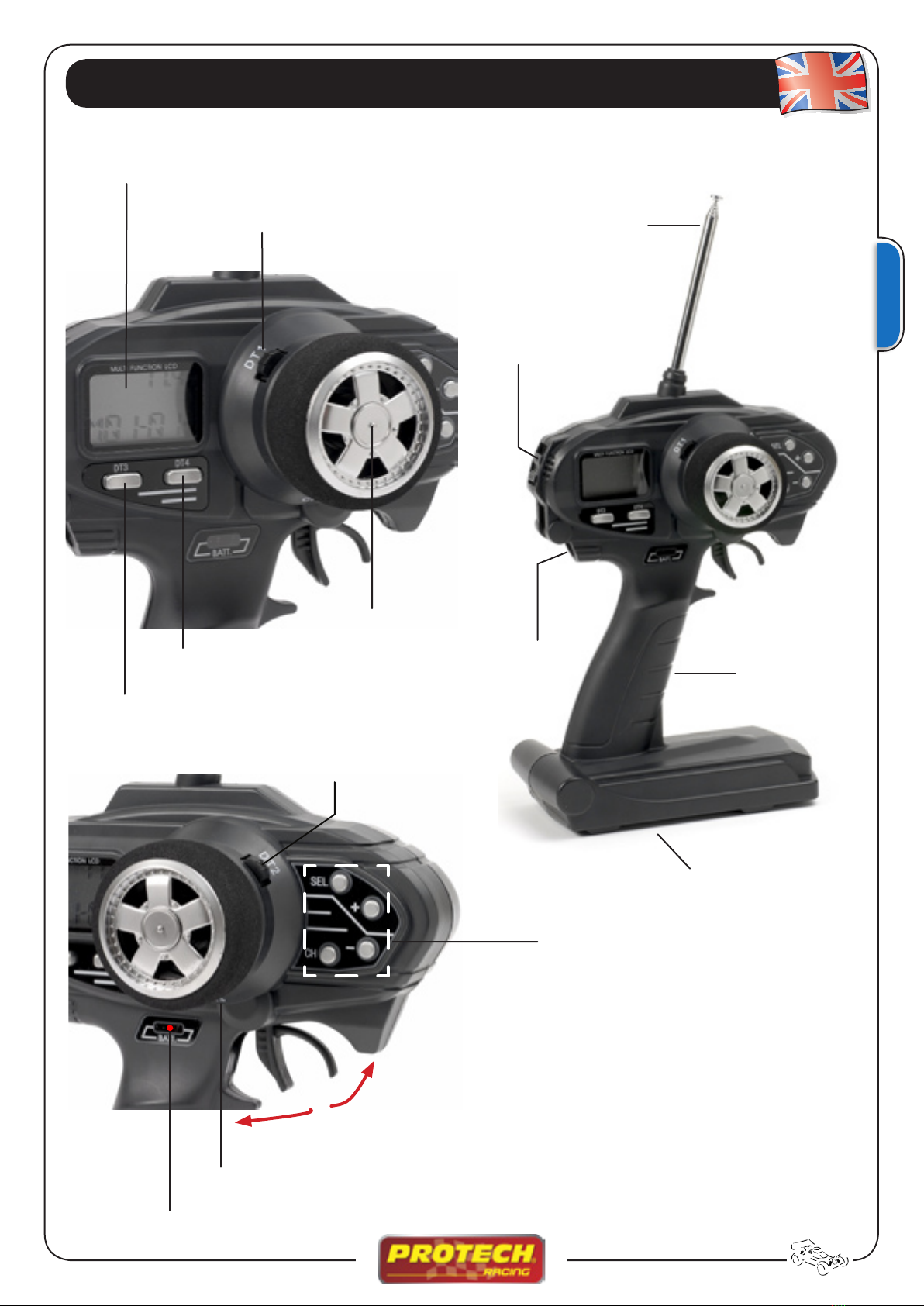
• LCD display
• LED indicator
• 10 models memory
• 3 Channels
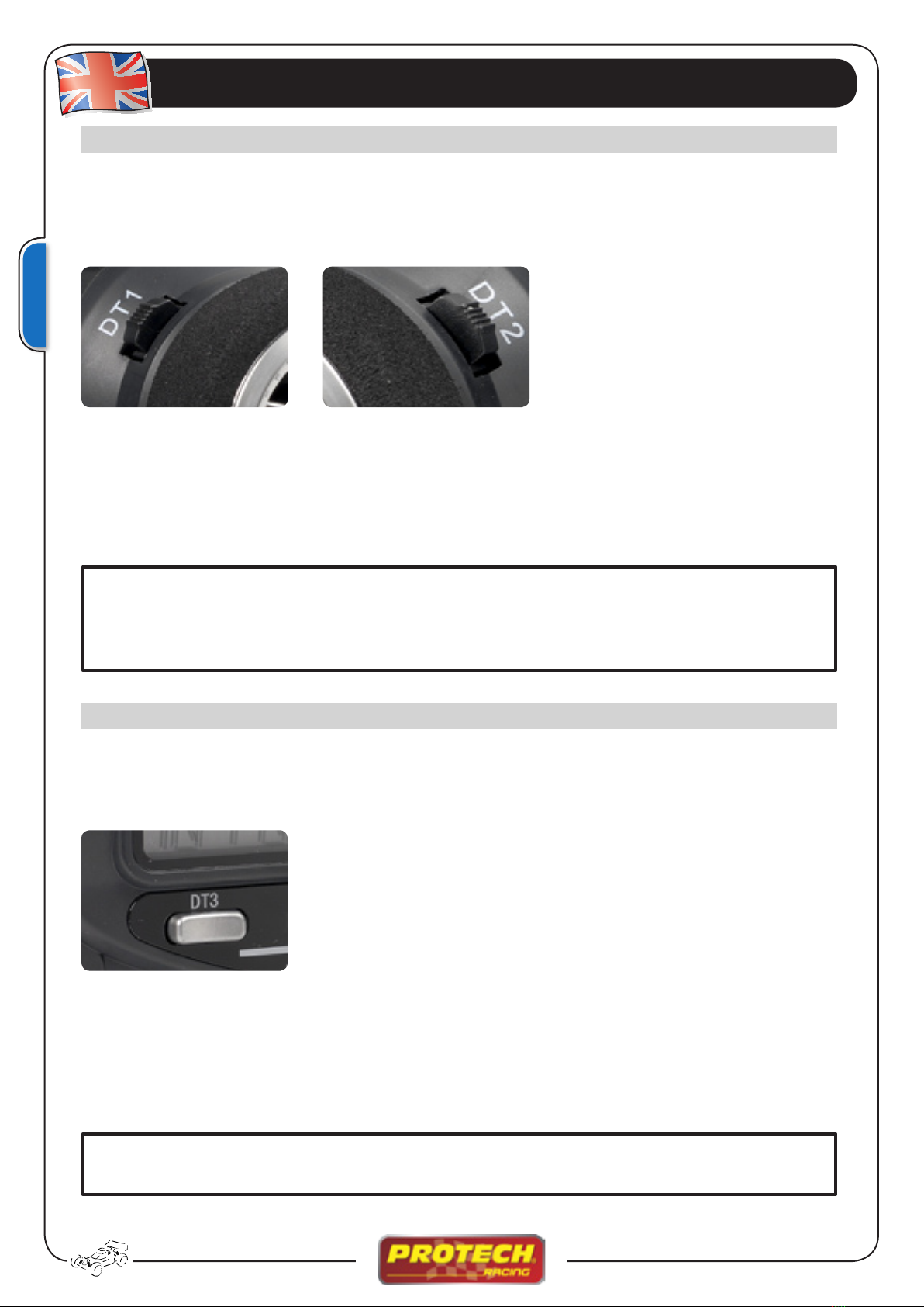
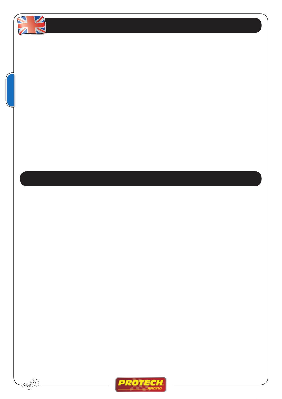
• Digital Trim
• Steering wheel
• Charging jack
• Low battery alarm
• Tone for digital trim
• EPA (End point adjustment)
• SPD (Steering speed)
• EXP (Exponential)
• ABS (ABS function)
• ACC (Throttle acceleration)
• BMX (Brake mixing)
• TRM (Trims)
• D/R (Steering dual rate)
• ATL (Throttle ATL function)
• CH3 (Channel 3 position)
• SBT (Subtrim)
• REV (Servo reverse)
• M01 (Model select)