Prodigit 33501 Series User manual

33501 Series
High power
Electronic Load
Operation manual
S/N:90033503 REV:G

Material Contents Declaration
(材料含量宣称)
Hazardous Substance (有毒有害物质或元素)
(Part Name)
零件名称 铅
(Pb) 汞
(Hg) 镉
(Cd) 六价铬
(Cr6+)
多溴
联苯
(PBB)
多溴
二苯醚
(PBDE)
PCBA
(印刷电路装配件)X O X O O O
Electrical part not on PCBA’s
未在PCBA上的电子零件 X OX O O O
Metal parts
金属零件 O O O X O O
Plastic parts
塑料零件 O O O O X X
Wiring
电线 X O O O O O
Package
封装 X O O O O O
对销售之日的所售产品,本表显示, PRODIGIT 供应链的电子信息产品可能包含这些物质。注意:在所售产品中可能
会也可能不会含有所有所列的部件。This table shows where these substances may be found in the supply chain
of Prodigit electronic information products, as of the date of sale of the enclosed product. Note that some of the
component types listed above may or may not be a part of the enclosed product. ○:表示该有毒有害物质在该部
件所有均质材料中的含量均在SJ/T 11363-2006 标准规定的限量要求以下。○:Indicates that the concentration of
the hazardous substance in all homogeneous materials in the parts is below the relevant threshold of the SJ/T
113632006 standard. ×:表示该有毒有害物质至少在该部件的某一均质材料中的含量超出SJ/T 11363-2006 标准
规定的限量要求。×:Indicates that the concentration of the hazardous substance of at least one of all
homogeneous materials in the parts is above the relevant threshold of the SJ/T 11363-2006 standard.
Note(注释):
1.Prodigit has not fully transitioned to lead-free solder assembly at this moment;However, most of the
components used are RoHS compliant.
(此刻,Prodigit 并非完全过渡到无铅焊料组装;但是大部份的元器件一至于RoHS的规定。)
2. The product is labeled with an environment-friendly usage period in years.
The marked period is assumed under the operating environment specified in the product specifications.
(产品标注了环境友好的使用期限制(年)。所标注的环境使用期限假定是在此产品定义的使用环境之下。)
Example of a marking for a 10 year period:
(例如此标制环境使用期限为10年)

VERIFICATION of conformity with CE Directives Verification No: ACT201078CE
SAFETY SYMBOLS
Direct current (DC)
Alternating current (AC)
Both direct and alternating
Three-phase alternating current
Off (Supply)
On (Supply)
Protective earth (ground)
Caution!Refer to this manual before using the meter.
Caution, risk of electric shock
CAT IV – Is for measurements performed at the source of the low-voltage installation.
CAT III – Is for measurements performed in the building installation.
CAT II – Is for measurements performed on circuits directly connected to the low-voltage
installation.
CAT I – Is for measurements performed on circuits not directly connected to Mains.
This equipment is not for measurements performed for CAT II, III, and IV.
Fuse

Approved by:
Vincent Tan
Acts Certification and Testing Services
2008/5/6
Document holder:
Prodigit Electronics Co., Ltd.
Type of product:
DC Electronic Loads
Type designation:
33501, 33511, 33521, 33531, 33541, 33512,33513,33514,33515,33532,33533
Technical data:
115/230 Vac, 50 / 60 Hz, 300 W,
Class I
A sample of the product has been assessed with respect to CE-marking according to the Low Voltage
Directive (73/23/EEC & 93/68/EEC) and EMC Directive (89/336/EEC, 92/31/EEC, & 93/68/EEC) and
Found to comply with the essential requirements of the Directives.The Standard(s) used for showing
the compliance and the full details of the results are given in the Test Reports as detailed below:
Standard(s) Report No. Report Issued Date
IEC/EN 61010-1: 2001 ACT201078 December 14, 2005
EN 61326+A1+A2+A3, EN 55011+A1+A2, EN 61000-3-2,
EN 61000-3-3+A1, EN 61000-4-2+A1+A2, EN 61000-4-3+A1,
EN61000-4-4+A1+A2, EN61000-4-5+A1, EN 61000-4-6+A1,
EN 61000-4-8+A1, EN 61000-4-11
E940757
November 23,2005
The holder of the verification is authorized to use this verification in connection with the EC
declaration Of conformity according to the Directives. The CE marking may only be used if all
releveant and effective EC Directives are complied with. Together with the manufacturer's own
documented production control,The manufacturer (or his European authorized representative) can in
his EC Declaration of Conformity Verify compliance with the directives.

33501Series High Power Electronic load operation manual
Table of Contents
CHAPTER 1 INTRODUCTION............................................................................................................1-1
1-1. GENERAL DESCRIPTION...............................................................................................................1-1
1-2. FEATURES ..................................................................................................................................1-9
1-3. ACCESSORIES ............................................................................................................................1-9
1-4. OPTION.......................................................................................................................................1-9
1-5. SPECIFICATIONS .........................................................................................................................1-9
CHAPTER 2 INSTALLATION .............................................................................................................2-1
2-1. INSPECTION ................................................................................................................................2-1
2-2. CHECK LINE VOLTAGE.................................................................................................................2-1
2-3. GROUNDING REQUIREMENTS.......................................................................................................2-2
2-4. ADJUST THE FEET.......................................................................................................................2-2
2-5. RACK MOUNT..............................................................................................................................2-2
2-6. ENVIRONMENTAL REQUIREMENTS................................................................................................2-2
2-7. REPAIR.......................................................................................................................................2-2
2-8. GPIB CONNECTION.....................................................................................................................2-3
2-8. GPIB CONNECTION.....................................................................................................................2-3
2-9. RS-232C CONNECTION...............................................................................................................2-4
2-10.REMOTE CONTROL PORT ...........................................................................................................2-4
2-11 ANALOG PROGRAMMING BNC INPUT .......................................................................................2-5
2-12 POWER ON STATUS..................................................................................................................2-5
2-13 STORE /RECALL OPERATION ...............................................................................................2-5
2-14 AUTO SEQUENCE TESTING FUNCTION DESCRIPTION..............................................................2-7
2-15. LOAD CURRENT SLEW RATE SETTING.......................................................................................2-10
CHAPTER 3 OPERATION ..................................................................................................................3-1
3-1. FRONT PANEL DESCRIPTION AND 3-1-1 33501 EXTERNAL DIAGRAM ............................................3-1
3-2. INITIAL SETTING OF 33501 SERIES LOAD MODULE ......................................................................3-12
3-3 INPUT TERMINAL AND WIRE CONSIDERATION ...............................................................................3-17
3-4. LOAD CURRENT COURSE/FINE INCREASE/DECREASE ADJUSTMENT KNOB....................................3-18
3-5. I-MONITOR ................................................................................................................................3-22
3-6. PROTECTION FEATURES............................................................................................................3-23
CHAPTER 4 GPIB/RS-232 PROGRAMMING OPERATION..............................................................4-1
4-1. INTRODUCTION............................................................................................................................4-1
4-2. THE SUMMARY OF RS-232 INTERFACE AND COMMAND.................................................................4-1
4-3. GPIB/RS-232 COMMAND LIST................................................................................................4-2
4-4. THE DESCRIPTION OF ABBREVIATION...........................................................................................4-4
4-5. GPIB COMMAND DESCRIPTION ....................................................................................................4-5
CHAPTER 5 APPLICATIONS.............................................................................................................5-1
5-1. LOCAL SENSE CONNECTIONS.......................................................................................................5-1
5-2. REMOTE SENSE CONNECTIONS....................................................................................................5-2
5-3. CONSTANT CURRENT MODE APPLICATION....................................................................................5-3
5-4. CONSTANT VOLTAGE MODE APPLICATION....................................................................................5-5
5-5. CONSTANT RESISTANCE MODE APPLICATION...............................................................................5-6
5-6. CONSTANT CURRENT SOURCE OPERATION...................................................................................5-7
5-7. ZERO-VOLT LOADING APPLICATION .............................................................................................5-7

FIGURES
Fig 1-1.1 33501 0-60V / 0-240A 2400W Power Contour ....................................................1-1
Fig 1-1.2 33511 0-60V / 0-240A 3600W Power Contour ....................................................1-1
Fig 1-1.3 33521 0-60V / 0-480A 2400W Power Contour ....................................................1-2
Fig 1-1.5 33541 0-60V / 0-720A 3600W Power Contour ....................................................1-2
Fig 1-1.6 33512 0-60V / 0-360A 5400W Power Contour ....................................................1-3
Fig 1-1.7 33513 0-60V / 0-480A 7200W Power Contour ....................................................1-3
Fig 1-1.8 33514 0-60V / 0-600A 9000W Power Contour ....................................................1-4
Fig 1-1.9 33515 0-60V / 0-720A 10800W Power Contour ..................................................1-4
Fig 1-1.10 33532 0-60V / 0-720A 5400W Power Contour ..................................................1-5
Fig 1-1.11 33533 0-60V / 0-960A 7200W Power Contour ..................................................1-5
Fig 1-2 Constant Current mode..........................................................................................1-6
Fig 1-3 Constant Resistance mode....................................................................................1-6
Fig 1-4 Constant Voltage mode..........................................................................................1-6
Fig 1-5 Constant Power mode............................................................................................1-7
Fig 1-6 Dynamic Wave form................................................................................................1-7
Fig 1-7 Rise Time Transition Limitation ............................................................................1-8
Fig 1-8 Block Diagram of 33501 Series Electronic Load................................................1-13
Fig 2-1 SET OF SWITCH......................................................................................................2-1
Fig 2-2 AC LINE RECEPTACLE ..........................................................................................2-1
Fig 2-3 33501 FRONT/REAR PANEL ..................................................................................2-3
Fig 2-4 33501 Series High Power Load Rear panel...........................................................2-4
Fig 2-5 Diagram of Remote Control Port...........................................................................2-4
Fig 2-6 Analog programming load current in CC mode operation..................................2-5
Fig 2-7 front panel key switch ............................................................................................2-5
Fig 2-8 AUTO SEQ function operation flow chart.............................................................2-7
Fig 2-9 STORE (EDIT) MODE OPERATIONO FLOW-CHART............................................2-8
Fig 2-10 TEST MODE OPERATION FLOW-CHA................................................................2-9
Fig 2-11 The relationship of load current load ON/OFF, load level and output voltage of
DC power supply at turn ON .....................................................................................2-10
Fig 3-1 33501-Series High Power Front Panel ..................................................................3-1
Fig 3-2 33501 Series High Power electronic load.............................................................3-2
Fig 3-3 Remote sense connection on front panel(when current ≦60A)......................3-11
Fig 3-4 Remote sense connection on rear panel(When current >60A).........................3-11
Fig 4-1 RS-232 INTERFACE DIAGRAM..............................................................................4-1
Fig 5-1 Local voltage sense connections..........................................................................5-1
Fig 5-2 Remote voltage sense connections......................................................................5-2
Fig 5-3 constant mode application ....................................................................................5-3
Fig 5-4 Dynamic load current with independent programmed Rise/Fall slew rate........5-4
Fig 5-5 Constant Voltage mode application......................................................................5-5
Fig 5-6 Constant Resistance mode Application ...............................................................5-6
Fig 5-7 Constant current source connection....................................................................5-7
Fig 5-8 Zero-Volt loading connection ................................................................................5-7

Tables
Table 1-1 AC INPUT Specifications....................................................................................1-9
Table 3-1 33501 initialize...................................................................................................3-12
Table 3-2 33511 initialize...................................................................................................3-12
Table 3-3 33521 initialize...................................................................................................3-13
Table 3-4 33531 initialize...................................................................................................3-13
Table 3-5 33541 initialize...................................................................................................3-14
Table 3-6 33512 initialize...................................................................................................3-14
Table 3-7 33513 initialize...................................................................................................3-15
Table 3-8 33514 initialize...................................................................................................3-15
Table 3-9 33515 initialize...................................................................................................3-16
Table 3-10 33532 initialize.................................................................................................3-16
Table 3-11 33533 initialize.................................................................................................3-16
Table 3-12 the resolution of range I/II vs. Course/Fine load setting Key......................3-21
Table 4-1 GPIB/RS-232 SETTING COMMAND SUMMARY................................................4-2
Table 4-2 GPIB/RS-232 QUERY COMMAND SUMMARY...................................................4-3
Table 4-3 GPIB command terminator.................................................................................4-4
Table 4-4 PROT status byte register................................................................................4-14

33501 Series Operation Manual 1-1
Chapter 1 Introduction
1-1. General description
The 33501 Series Electronic Load is designed to test, evaluation and burn-in of DC power
supplies and batteries. The 335011 Series electronic load can be operated for manual and
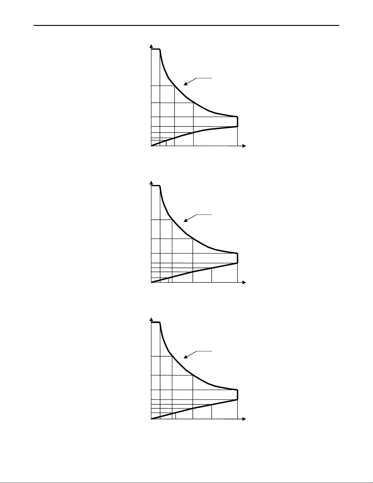
GPIB operation. The power contour of 33501 1800 Watts Electronic Load is shown in Fig 1-
1.1~1-1.5, it has an input from 0-360A, and 0 -60V current and voltage operating range
respectively. The power contour of 33501 series. The prodigit 33501 Series high power
electronic Load can be controlled locally at the front panel or remotely via computer over the
GPIB/RS-232C. Current (CC) mode, Constant Resistance (CR) mode, and Constant Voltage
(CV) mode. and Constant Power ( CP ) mode. The wide range dynamic load with
independent rise and fall current slew rate and analog programming input with arbitrary
wave-form input is available in Constant Current mode.
Fig 1-1.1 33501 0-60V / 0-240A 2400W Power Contour
Fig 1-1.2 33511 0-60V / 0-240A 3600W Power Contour
3600W CONTOUR
240 A60 90 120 180
60
40
30
0.4
Current
0.1
15
0.2
0
0.3
Voltage
2400W CONTOUR
240 A
40 120 160
60
20
15
0.6
Current
0.1
10
0.3
0
0.4
Voltage
1-2 PRODIGIT
Fig 1-1.3 33521 0-60V / 0-480A 2400W Power Contour
Fig 1-1.4 33531 0-60V / 0-480A 3600W Power Contour
Fig 1-1.5 33541 0-60V / 0-720A 3600W Power Contour
3600W CONTOUR
720 A
60 90 102.85 360 480
60
40
10
0.7
Current
0.1
5
0.35
0
Voltage
0.46
3600W CONTOUR
480 A
60 80 90 240 360
60
40
15
0.6
Current
0.1
7.5
0.3
0
Voltage
2400W CONTOUR
480 A
40 68.57 120 240
60
20
10
0.7
Current
0.1
5
0
0.35
Voltage
0.175
0.45

33501 Series Operation Manual 1-3
Fig 1-1.6 33512 0-60V / 0-360A 5400W Power Contour
Fig 1-1.7 33513 0-60V / 0-480A 7200W Power Contour
5400W CONTOUR
360 A
90 135 180 270
60
40
30
0.4
Current
0.1
15
0.3
0
0.2
Volta
g
e
7200W CONTOUR
480 A
120 180 240 360
60
40
30
0.4
Current
0.1
15
0.3
0
0.2
Volta
g
e
This manual suits for next models
11
Table of contents
Other Prodigit Power Supply manuals