Connecting the Pump and Controller
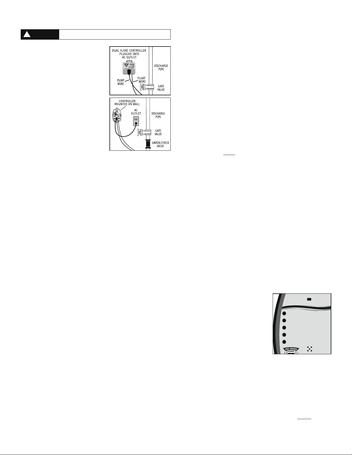
Dual Float Controller
Plug the control box into a properly grounded,
3-prong receptacle, then insert the pump plug into
the receptacle on the control box.
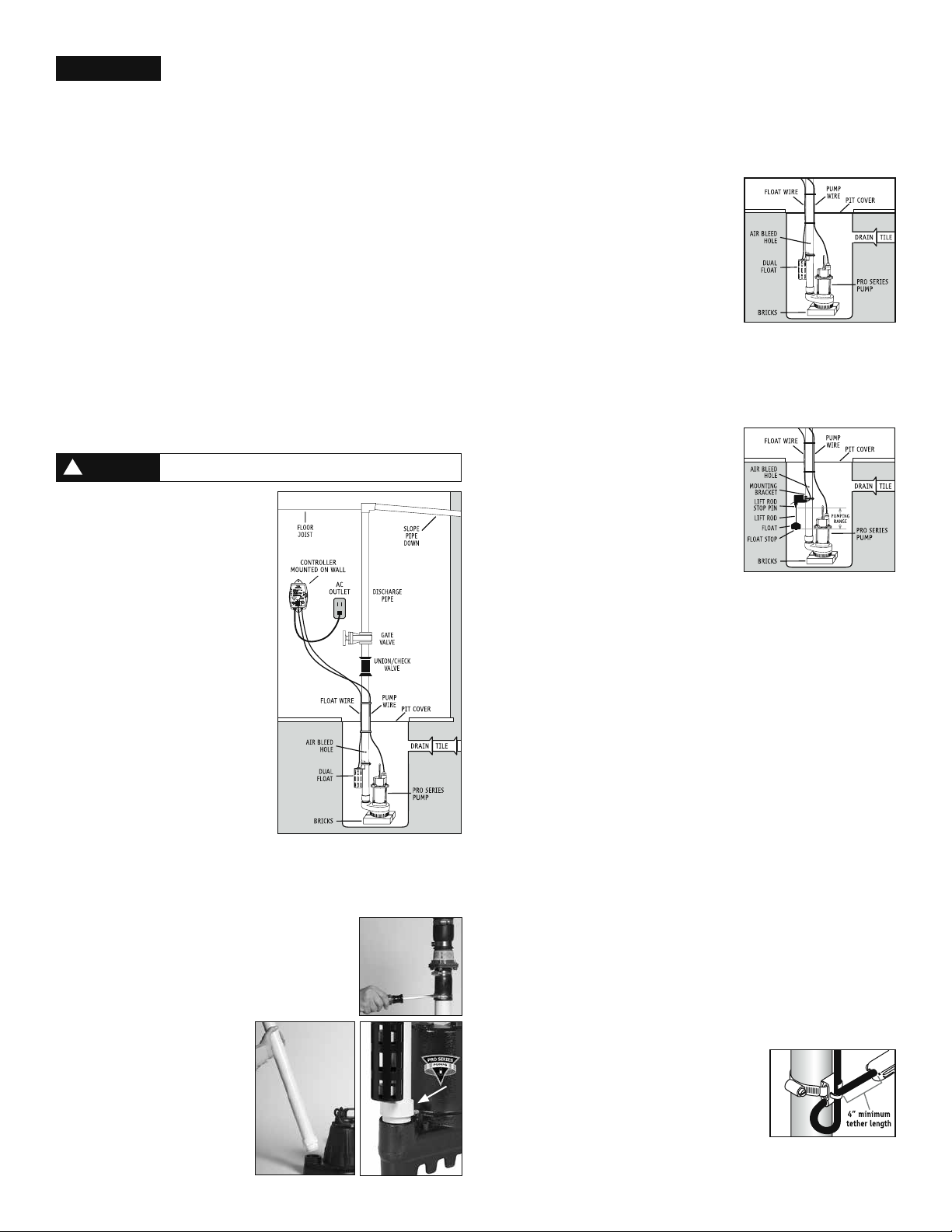
For a neater installation, secure the power cord and
the float switch cord to the discharge pipe with
wire ties or hose clamps. Keep the cords separated
from each other on opposite sides of the pipe.
Enhanced Controller
1. Mount the controller to the wall through the 2
holes on the cabinet using proper mounting
hardware for the application. The controller
should be mounted at least 4’ from the floor
and 1’ from the outlet.
2. Check to ensure the float switch is connected
to the controller. The float switch wire of
the Enhanced Controller includes a connector
that can be separated from the controller
when the wire needs to be threaded through
small openings. When used with the Enhanced
Controller, the Dual Float Switch has a safety
locking pin. This pin will prevent the float switch from accidently being disconnected
from the controller. Check to ensure the safety locking pin is inserted through the
connector.
3. Plug the control box into a properly grounded, 3-prong receptacle. Then, plug the
pump into the receptacle on the control box. Do not use an extension cord.
4. Using a flathead screwdriver, adjust the dial on the front of the controller to select
the number of seconds that the pump will run after the float drops. The dial can be
adjusted from 5-45 seconds. The manufacturer default is about 10 seconds.
Deluxe and Ultimate Controllers
1. Mount the controller to the wall through the 2 holes on the cabinet using the proper
mounting hardware for the application. The controller should be mounted at least 4’
from the floor and within 2’ of the outlet.
2. Check to ensure the float switch is connected to the controller. The float switch wire
of the controller includes a connector that can be separated from the controller when
the wire needs to be threaded through small openings. When used with the Deluxe
or Ultimate Controller, the Dual Float Switch has a safety locking pin. This pin will
prevent the float switch from accidently being disconnected from the controller.
Check to ensure the safety locking pin is inserted through the connector.
3. Open the plastic door on the top of the controller, and using a flathead screwdriver,
adjust the dial to select the number of seconds that the pump will run after the float
drops. The timer can be adjusted from 5-45 seconds. The manufacturer default is
about 10 seconds. Install a 9V alkaline battery and replace the plastic door.
4. Plug the control box into a properly grounded, 3-prong receptacle. Then, plug the
pump into the receptacle on the control box. Do not use an extension cord.
5. Make sure the Power Failure Alarm slide switch is in the ON position.
Connecting to a Security System (Deluxe and Ultimate Controllers Only)
The Deluxe and Ultimate Controllers include a terminal on the right side of the control
box to connect to a security system or other alarm devices. There are (3) three positions
for wire connections on this terminal: N.O. – normally open, N.C. – normally closed, and
Common.
1. Check your security system to determine whether an open (no contact) or closed
(making contact) connection is needed to activate the alarm.
2. The security system will provide (2) two connection terminals to extend wires to
the control terminal. Strip two wires 1/4” each. Connect either wire to the common
terminal. To secure the wire into the terminal, insert the exposed wire into the hole
on the side of the terminal next to the screw marked common. Turn the screw a few
turns to lock in the wire.
3. If the security system requires a closing of a contact to activate the alarm, secure the
other wire into the terminal hole labeled N.O. (normally open). If the security system
requires an opening of a contact, secure the wire into the terminal hole labeled N.C.
(normally closed).
Connecting the Pump and Float Switch (Models VS and TS – No Controller)
1. Plug the float switch cord into a properly grounded 3-prong receptacle. Then, plug
the pump into the receptacle on the float switch cord. Do not use an extension cord.
Completing the Installation (all models)
1. After the initial installation, be sure to check the pump operation by filling the sump
with water and observing the pump through several full cycles. When using the
Enhanced or Deluxe Controllers, the pump should run for 10 seconds (preset from
the factory and adjustable on the Enhanced, Deluxe and Ultimate controller) after
the float drops. Note: When the pump activates, it should have a “normal pumping”
sound. Any abnormal sound, vibration, or lack of output is the signal of a problem.
Stop the pump and refer to the troubleshooting guide. The Vertical Float Switch
and Tether Float Switch must be moving freely at all times. Make sure the float
switch does not come into contact with other pumps, wires, pipes or any other
object that may be in the sump pit. The float switch must not come into contact
with the sump pit floor or wall. If the float switch does not move freely, the
pump will not activate.
2. Replace the pit cover making sure not to pinch or crimp the pump wire with the
cover. The pit cover either has a ‘hole punch’ that will allow the cord to be passed
through or one can be drilled in the cover.
Product Operation
Dual Float Switch
The Dual Float Switch contains two large floating rings enclosed within a protective
cage. Water will lift the bottom float by a 1⁄4”, which will activate the pump. If for
any reason the lower float does not activate the pump, the water will rise and activate
the second switch. As the pump evacuates the water from the pit, the floats will drop.
The pump will run for an additional 10 seconds (preset from the factory and adjustable
on the Enhanced, Deluxe and Ultimate controller) after the float drops. When using the
Dual Float Switch with the Enhanced, Deluxe or Ultimate controller, the float switch wire
will include a connector that can be separated from the controller when the wire needs
to be threaded through small openings. The float switch connector has a safety locking
pin. This pin will prevent the float switch from accidentally being disconnected from the
controller. To remove the pin, push the pointed end of the pin into the float connector
and pull it out from the other end. The float switch wire can now be disconnected. Make
sure to reinstall the pin after the float switch is reconnected. Note: When mounting the
float switch, position the bottom of the cage at the height you want the pump to activate.
Vertical Float Switch with Enhanced, Deluxe or Ultimate Controllers
The Vertical Float Switch contains a single large float. Water will lift the float by a 1⁄2”,
which will activate the pump. As the pump evacuates the water from the pit, the float
will drop. The pump will run for an additional 10 seconds (preset from the factory and
adjustable) to evacuate the pit completely after the float drops. Note: There are two
rubber stoppers on the float switch rod. Do not remove or alter their position as it will
disrupt the timing of the controller and how long the pump runs. Note: When mounting the
float switch, position the bottom of the float at the height you want the pump to activate.
Tether Float Switch with Enhanced, Deluxe or Ultimate Controllers
The Tether Float Switch contains a single float connected to a flexible tether. Water will
raise the float to activate the pump. As the pump evacuates the water from the pit the
float will fall and the pump will run for an additional ten seconds to empty the pit.
Note: The Tether Float Switch must be moving freely at all times. If the float switch
does not move freely the pump will not activate.
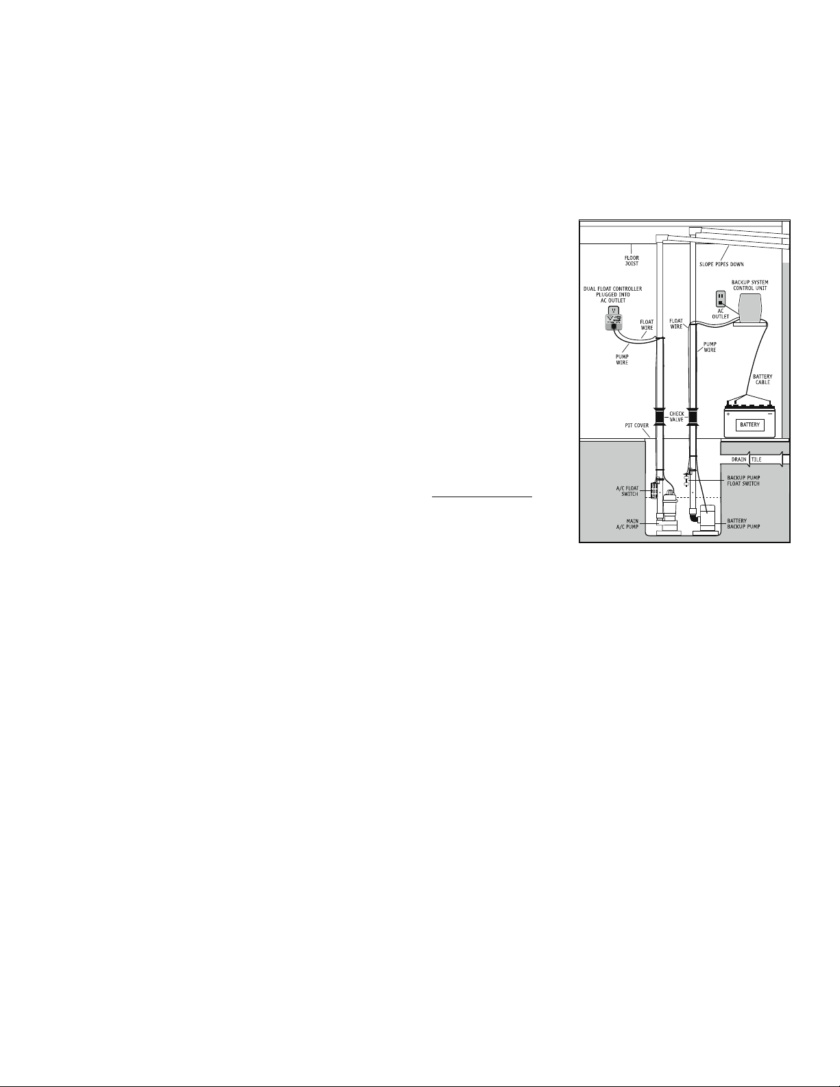
Dual Float Controller
The Dual Float Controller will activate the pump when either float is lifted, and then
shuts off automatically 10 seconds after the float drops. Plug the pump cord into the
piggyback switch on the control unit.
Enhanced Controller
The Enhanced Controller features a dial to adjust the number of seconds that the
pump will run after the float drops. The dial can be adjusted from 5-45 seconds. The
manufacturer default is about 10 seconds. The LED on the front of controller will signal
the unit is receiving power. The controller will also run the pump once a week for
approximately four (4) seconds. This test will exercise the pump and help ensure the
pump is working properly.
Deluxe and Ultimate Controllers
The Deluxe and Ultimate Controllers feature a series
of warnings (audible and visual) that pinpoint
potential problems with the pump, switch and
power conditions. The controller will sound an alarm
when power has been interrupted, when the pump
has run for more than 10 minutes continuously, or
when the 9V battery is low. The 9V battery (sold
separately) runs the controller during a power
outage, allowing it to sound an alarm if the circuit
breaker trips, the controller is not plugged in
securely, or the home’s power is interrupted. Note:
The 9V battery will only power the controller, not the pump. The controller is equipped with
a USB data port. The purpose of this port is to allow communication with the Pro Series
Connect Modules. The Pro Series Connect Modules are separately sold accessories that will
allow the user to stay connected and receive remote notifications of potential problems
and needed maintenance while away from home. The controller has a dial (located in the
battery compartment) to adjust the number of seconds that the pump will run after the
float drops. The controller will also run the pump once a week for approximately four (4)
seconds. This test will exercise the pump and help ensure the pump is working properly.
Operating the Pump in a Continuous-Duty Application
The S Series pump is rated for continuous duty and may be used in applications requiring
continuous pumping including fountains or ponds. For use in any continuous-duty
application the pump should be plugged directly into the wall outlet without the use of
the controller. The outlet must be a single-phase, properly grounded 3-prong receptacle,
115V, 60HZ. For continuous-duty operation, the pump must be submerged at least 3/4 of
the depth of the pump at all times.
Make sure the outlet is a single phase, 115V and 60HZ
for all the pump installations.
WARNING
!
Slide switch to OFF during power failures
to conserve battery energy and silence alarm
Power Failure Alarm
C
On Off
AC power is out
Make sure this controller is plugged into the wall outlet
Check the circuit breaker
The system is operating
Light should be flashing
Pump or float problem
The pump has run continuously for 10 minutes
Refer to the instructions for possible causes
High water alarm (optional feature)
Water has reached the high water sensor
9 volt battery low or slide switch is OFF
Replace 9 volt alkaline battery or move switch to ON
Deluxe
F
3