Pro's Kit MT-7071N User manual

1
MT-7071N
LCD Cable Length Toner & Probe Kit
User’s Manual
1st Edition, 2023
©2023Copyright by Prokit’s Industries Co., Ltd.

2
1. OVERVIEW
Thank you for purchase Pro’sKit MT-7071N LCD Cable Length
Toner & Probe Kit. The Toner and Probe set is used to measure
cable length and quickly trace and identify cables or wires within a
group and also check the operation of telephone lines. With proper
use and care, this instrument will provide many years of reliable
service.
MT-7071N is a new high-frequency filter circuit technology, with the
elimination of noise and anti-interference line tracker, LCD display
screen. Users can select display language in Chinese or English.
Suitable for ordinary network, PoE network, UTP / STP cable search
and positioning. The interface on the network can be located through
the port flashing function. Network Cable and BNC coax map test.
This product can perform the network wire length testing. This
product is suitable for telecommunications, network communication,
monitoring, CATV and other indoor and outdoor wiring construction
or maintenance projects.
Caution
!This product uses 9V 6LR61 or 6F22 battery power supply, and
6LR61 battery is recommended.
!To save the battery, please shut down immediately after use. If it
is not in use for a long time, please remove the battery in the
transmitter and receiver to avoid damage to the product caused by
battery liquid from leaking out.
!This product is strictly prohibited to access the live lines above
voltage DC 60V or any AC voltage.
!Please do not perform related operations on the communication
line during thunderstorms to prevent lightning strikes and personal
safety.
!Do not place this product in dusty, wet and temperatures above
40℃.
!Please do not disassemble the device. Repair and maintenance
should be done by a professional staff.

3
2.Diagram
Transmitter and Remote Unit Diagram
① RJ45(with LED) connector:For Cable Length and Port Flash test
② RJ45 connector:For Cable map、Cable Tracing.
③ BNC connector: For Coax map、Coax Tracing
④ LCD display.
⑤ “ ” key:ENTER key: Press this key for a test choose or setting.
⑥ “ ” key:Press this key to move arrow cursor up or left on LCD
to choose function.
⑦ “ ” key:Press this key to return to previous menu.
⑧ “ ”:Press this key to power on, and long push again for power
off.
⑨ “ ”:Press this key to move arrow cursor down or right on LCD
to choose function.
⑩ Battery cover.

4
Receiver Diagram
① Probe:Used for cable tracing and NCV detection.
② LED light
③ Power ON/OFF indicator
④ NCV indicator
⑤ Signal status indicator
⑥ Sensitivity control
⑦ Earphone socket (Φ3.5mm)
⑧ Function switch (LED light/NCV/OFF/SCAN mode)
⑨ Speaker
⑩ Locating and tracing cables function button
⑪ RJ45(8 pin)/ RJ11 (6/4/2 pin) cable mapping test
socket.
⑫ Battery cover

5
3.Operation
Do not connect with DC voltage over 60V or any AC
voltage live circuit equipment or it will result damage.
Press “ ”key to power on, as show blow. Press“ ” or“ ”key
to choose function. Press“ ”key to test. Press“ ”key to return.
Note: The arrow “▲” on the LCD display indicates the test port
location of the network cable to be tested.
graph 1 graph 2
Graph 1: The cable shall be inserted into the middle RJ45 connector.
Graph 2: The cable shall be inserted into the left RJ45(with LED)
connector .
3.1 Cable map test:
Ø Insert the pending network cable into the transmitter RJ45 socket in
the middle and the other end into the receiver socket or remote unit,
BNC coax into BNC socket.
Ø Select the “CONT” menu and press “ ” to test with test results
shown below:
UTP STP
!"#$%
▲
Type:Ca t5e/6/6a
Press ENTER Test
▲
Type:Cat.5e/6/6a
Start Test
Un it : Meter
Le ngth

6
Short disconnection crossover
Ø Telephone cable test results shown below:
6p6c 6p4c 6p2c
Ø BNC coax test results shown below:
Ø If the display "cable open " indicates that the network jumper is all
open or the other end of the network cable is not inserted in the test
remote or receiver, or the test interface is wrong.
3.2 Measure Cable Length:
During the test, the power consumption is large and the
battery power decline is fast. the test time should be interval
until the battery power is restored.
Ø Insert the pending network cable into the transmitter socket in the
left. Do not plug in any socket at the other end.
Ø Select the “Length” menu and press “ ” to test with test results
shown below:
▲
CONT

7
Ø Units of length can select “Meter” “Yard” “Foot” under the Units
menu.
Ø Because each pair of wire has different twisted density, it is normal
to measure the numbers slightly different, which can be measured
many times to get the same measurement value.
Ø From the image, it means there exists problem at 12.1m. To make
sure it is short or broke there, you can test it continuity to know
details.
■ NOTE: Kind reminds when measuring cable length.
1. The network cable to be tested must be de-energized.
2. Disconnect the cable at the far end, no remote, no other
devices connected!
3. The range must be 2.5m—200m, otherwise , it would be
display 0 meter.
3.3 Cables tracking:
Ø Connect one end of the target cable to the RJ45 socket in the
middle of the transmitter, BNC coax into BNC socket.
Ø Select the “SCAN” menu and press “ ” to transmit and shown
below:
▲
Typ e:Cat.5e/6/6a
Start Te st
Un it : Meter
Le ngth
▲

8
Ø The receiver function switch is switched on to the "Scan" or
"lighting" position.
Ø The receiver sensitivity knob is rotated clockwise to the maximum
(the arrow tail is above).
Ø Press and hold the "SCAN" button in the middle of the receiver,
while the probe is close to the network cable to be measured, the
speaker emits a clear "beep-beep " sound, and the network cable
contacted by the receiver probe is the target network cable to find.
Ø When tracking a cable in the working network, due to the network
switch, there may be audio signals adjacent to the target cable,
each cable can be removed to find the target cable or try to rotate
the receiver sensitivity knob counterclockwise to reduce the
reception sensitivity to find the target cable.
3.4 Port Flash & Switch details testing:
This function transmits the pulsing signal through the transmitter to
flashing the LED indicator of the network switch, then can locate the
interface of the network cable on the switch. At the same time, the
network switch working performance can be tested.
Do not connect with DC voltage over 60V or any AC
voltage live circuit equipment or it will result damage.

9
Ø Insert the network cable into the transmitter socket in the left.
Ø Select the “Flash” menu and press “ ” to start testing.
Ø The 2 indicators on the RJ45 jack port will be lit and flash. Then
observe the ports on switch, if there is a port whose flash frequency
is 3 secs, and slower than all the other ports, it tells you the port is
target one you’re looking for.
Ø Also, the device can tell you the connected switch’s information,
such as its speed (10M/100M/1000M), transmitting modes (FDX:
full duplex/ HDX: half duplex) Protocol (Auto- Nego / Non-Auto-
Nego). See the graph for ref. as below.
Ø If "Check Port" is displayed, the reasons may be: 1. Network cable
insertion error and test interface; 2. Network cable is not connected
to the switch; 3. Network cable fault. 4. Switch, router fault or
incompatibility with the instrument. 5. This instrument fails.
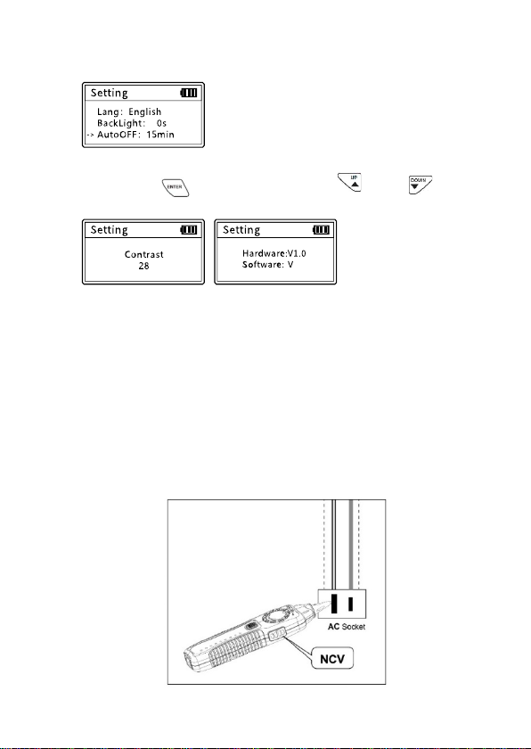
3.5 Setting:
This function can set the language (Chinese / English), backlight time,
automatic shutdown time, contrast, etc.
Ø Select the “Setting” menu and press “ ” to start setting.
Ø Backlight setting:
Adjust the backlight time among 5S, 10S, 15S, on and off.
Ch eck Port
&'(()*+
,
10
Ø Auto-off time setting:
Adjust the Auto-off time among 15mins, 30mins, 1hour, off.
Ø Contrast setting:
Press the “ ” to setting. And press “ ” or “ ”
key to adjust the contrast to suit yourself.
Ø Version information:
To c he c k v e rs io n in f or ma t io n o f so ftw a re a n d ha r dw a re . a s a bo v e.
3.6 Non-contact Voltage detection (NCV)
This function is used to determine whether the wire or equipment has
an AC voltage, the detection range AC90-1000V (50 / 60Hz).
Ø Push the receiver function switch to the NCV position, put the
receiver probe close to the target body, if the AC voltage is
detected, the speaker emits an alarm sound of different frequency,
the speaker rapid sound indicates a high voltage or fire line, the
slow sound may be low voltage or zero line.
-
./0
Table of contents
Languages:
Other Pro's Kit Test Equipment manuals

Pro's Kit
Pro's Kit NT-309 User manual

Pro's Kit
Pro's Kit MT-7071 User manual

Pro's Kit
Pro's Kit MT-7063 User manual

Pro's Kit
Pro's Kit MT-7062 User manual

Pro's Kit
Pro's Kit NT-305 User manual

Pro's Kit
Pro's Kit MT-7801 User manual

Pro's Kit
Pro's Kit MT-7068 User manual

Pro's Kit
Pro's Kit N2 Series User manual

Pro's Kit
Pro's Kit 8PK-4103IN User manual

Pro's Kit
Pro's Kit MT-7076 User manual


