Prime Karts FATAL VISION ROADSTER Instructions for use

BY
[ SINGLE SEATER ]
Step By Step
Assembly Instructions
and Maintenance Guide
[ 2 ] Fatal Vision® Roadster Assembly Instructions and Maintenance Guide | © Innocorp, ltd. www.fatalvision.com
FATAL VISION® ROADSTER STEP BY STEP ASSEMBLY INSTRUCTIONS [ SINGLE SEATER ]
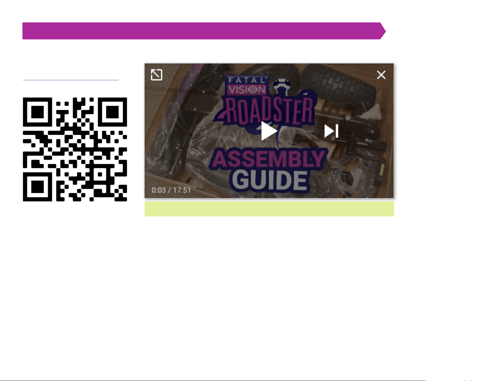
Scan QR code below or visit
https://vimeo.com/709244660 to
review the assembly guide video.
TO REFER TO THE ASSEMBLY VIDEO USE THE TIMESTAMPS THROUGHOUT THIS GUIDE
[ 3 ] Fatal Vision® Roadster Assembly Instructions and Maintenance Guide | © Innocorp, ltd. www.fatalvision.com
FATAL VISION® ROADSTER STEP BY STEP ASSEMBLY INSTRUCTIONS [ SINGLE SEATER ]
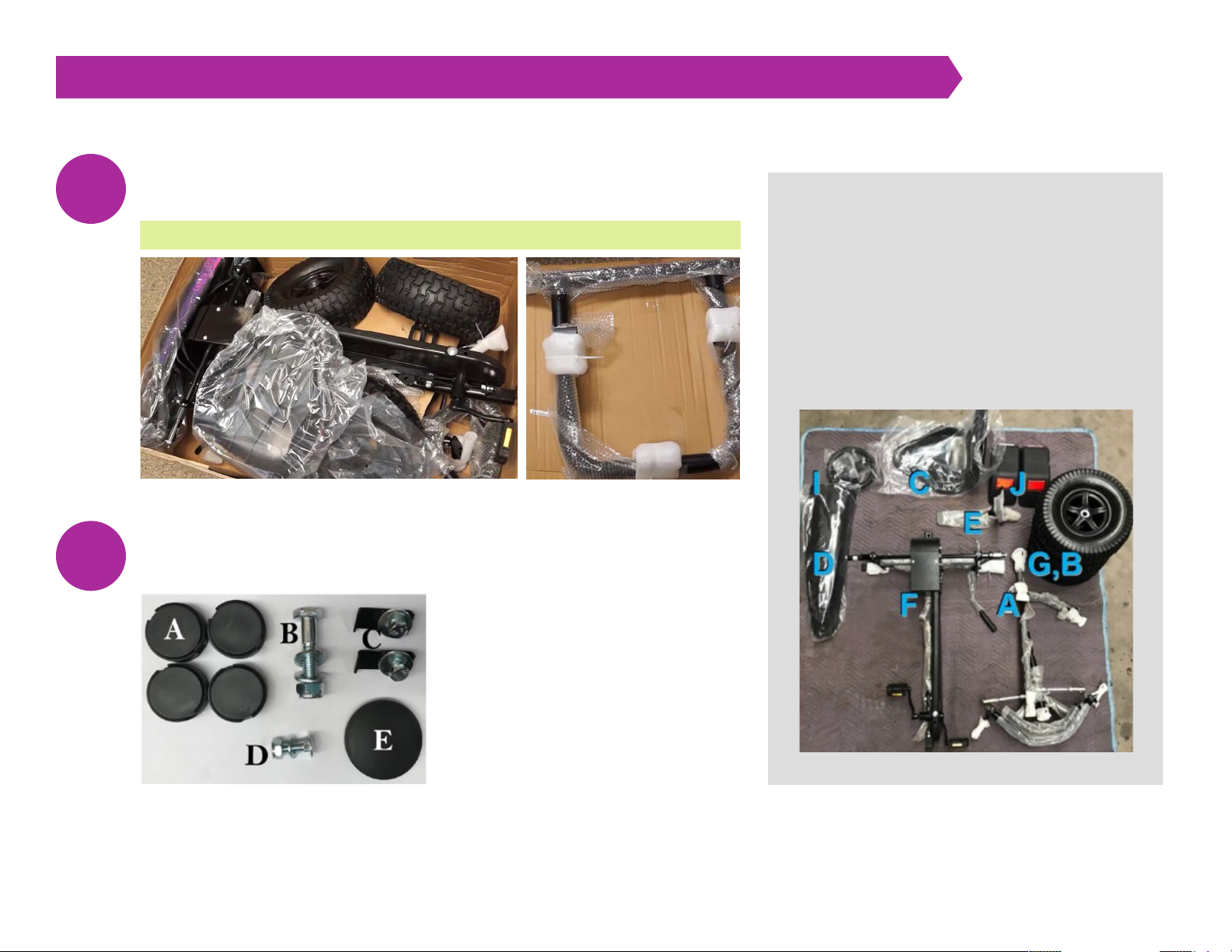
Unpack your Roadster. Remove the top box and lay out all pedal kart
components to verify that nothing is missing from the package.
Unpack the hardware set located inside the plastic steering wheel bag.
1
2
A: 1 front assembly
B: 1 drive wheel
C: 1 seat
D: 1 front spoiler
E: 1 hardware bag
J: 1 fender set
F: 1 rear assembly
G: 3 coast wheels
H: 1 bumper frame
(not shown below)
I: 1 sterring wheel
BOX CONTAINS THE FOLLOWING:
HARDWARE ASSEMBLY SET
INCLUDES:
A: 4 wheel hub caps
B: 1 frame connection bolt assembly
C: 2 spoiler mounting brackets
D: 1 seat/seat frame hardware
E: 1 steering wheel cap
VIDEO 0:10 UNPACK THE ROADSTER
[ 4 ] Fatal Vision® Roadster Assembly Instructions and Maintenance Guide | © Innocorp, ltd. www.fatalvision.com
FATAL VISION® ROADSTER STEP BY STEP ASSEMBLY INSTRUCTIONS [ SINGLE SEATER ]
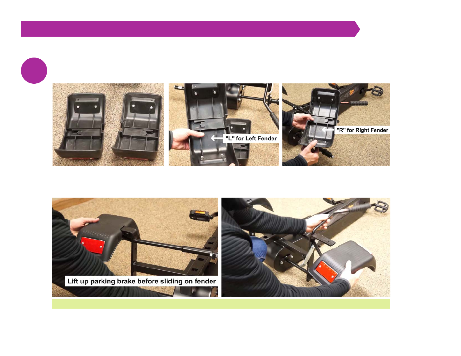
Install the rear fenders: Locate the two fenders and identify the left and right fenders by looking on the inside of
the fenders and finding L for left and R for right.
Install the fenders by sliding them over the fender support bracket as shown and lightly tap them on. You may need
to move the hand brake lever to install the fenders fully.
3
VIDEO 0:32 INSTALL THE FENDER SET
[ 5 ] Fatal Vision® Roadster Assembly Instructions and Maintenance Guide | © Innocorp, ltd. www.fatalvision.com
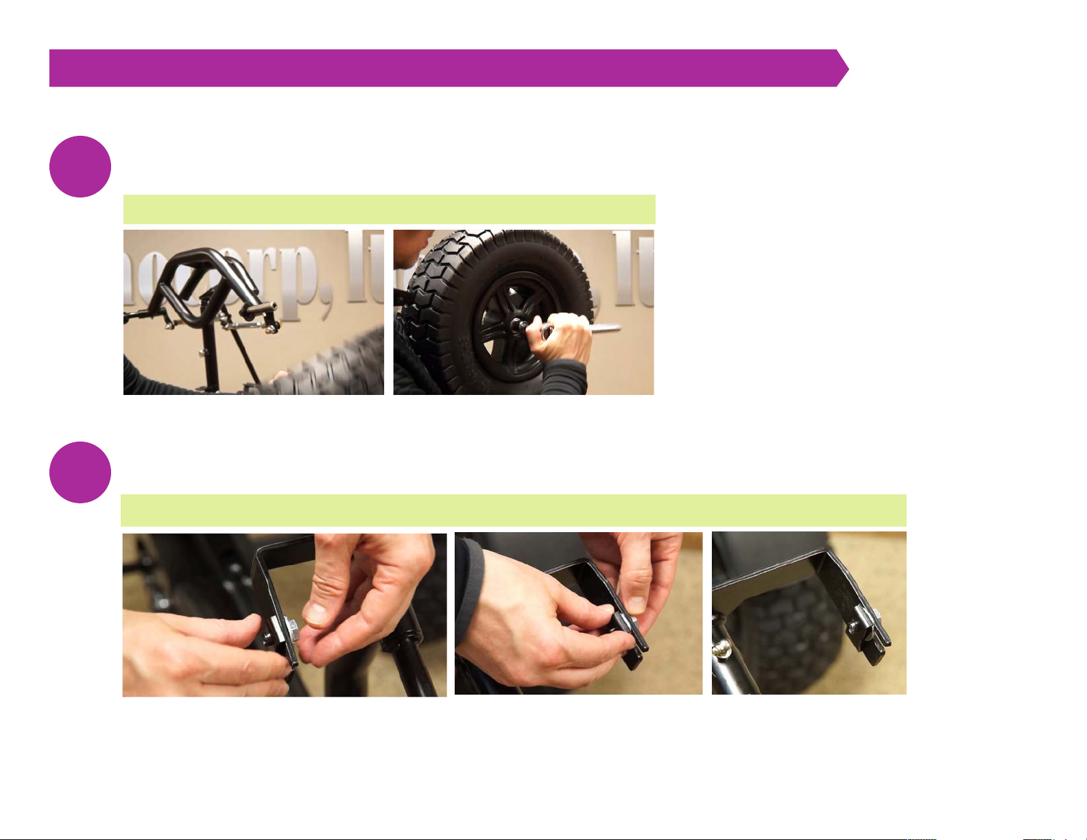
FATAL VISION® ROADSTER STEP BY STEP ASSEMBLY INSTRUCTIONS [ SINGLE SEATER ]
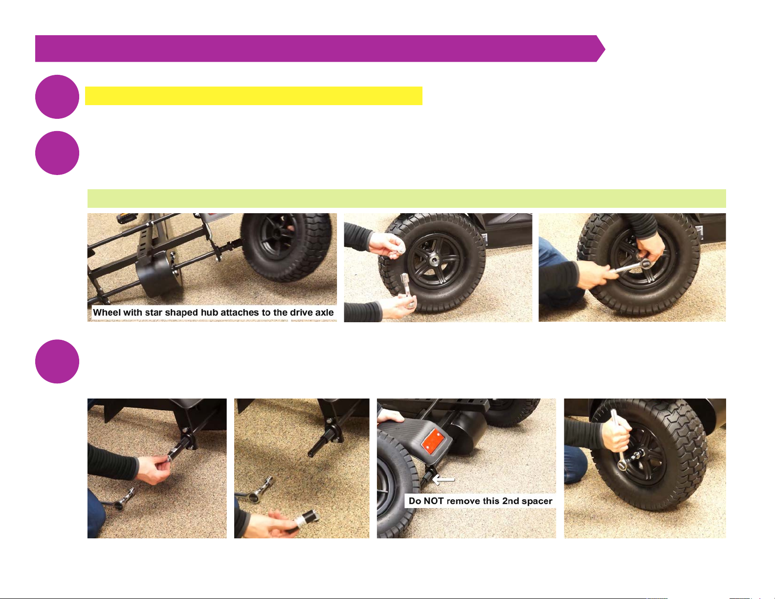
IMPORTANT: BEFORE ASSEMBLY, FILL THE TIRES TO 25 PSI.
Attach the Drive Wheel: The drive wheel does not have a bearing on each side like the coast wheels. Instead, there is a bushing on
one side and a star pattern on the other side. Using a 17mm socket, remove the bolt and washer from the drive side of the rear axle.
Slide the drive wheel over the square on the drive axle until the inside of the wheel makes contact with the stop washer. A rubber
mallet may be used. Reinstall the bolt and washer and tighten using a 17 mm socket.
Attach the coast wheel: Using a 17mm socket, remove the bolt and washer from the coast side of the rear axle and the first black
spacer. Slide the coast wheel on the axle with the air fill valve facing INWARD. Reinstall the bolt and washer and tighten using the
17mm socket. IMPORTANT: Remove the first black metal spacer tube with the silver sticker. DO NOT remove the second black
plastic spacer. The pedal chain drive will not work correctly without the second spacer.
5
4
6
VIDEO 1:13 ATTACH THE REAR WHEELS
[ 6 ] Fatal Vision® Roadster Assembly Instructions and Maintenance Guide | © Innocorp, ltd. www.fatalvision.com
FATAL VISION® ROADSTER STEP BY STEP ASSEMBLY INSTRUCTIONS [ SINGLE SEATER ]
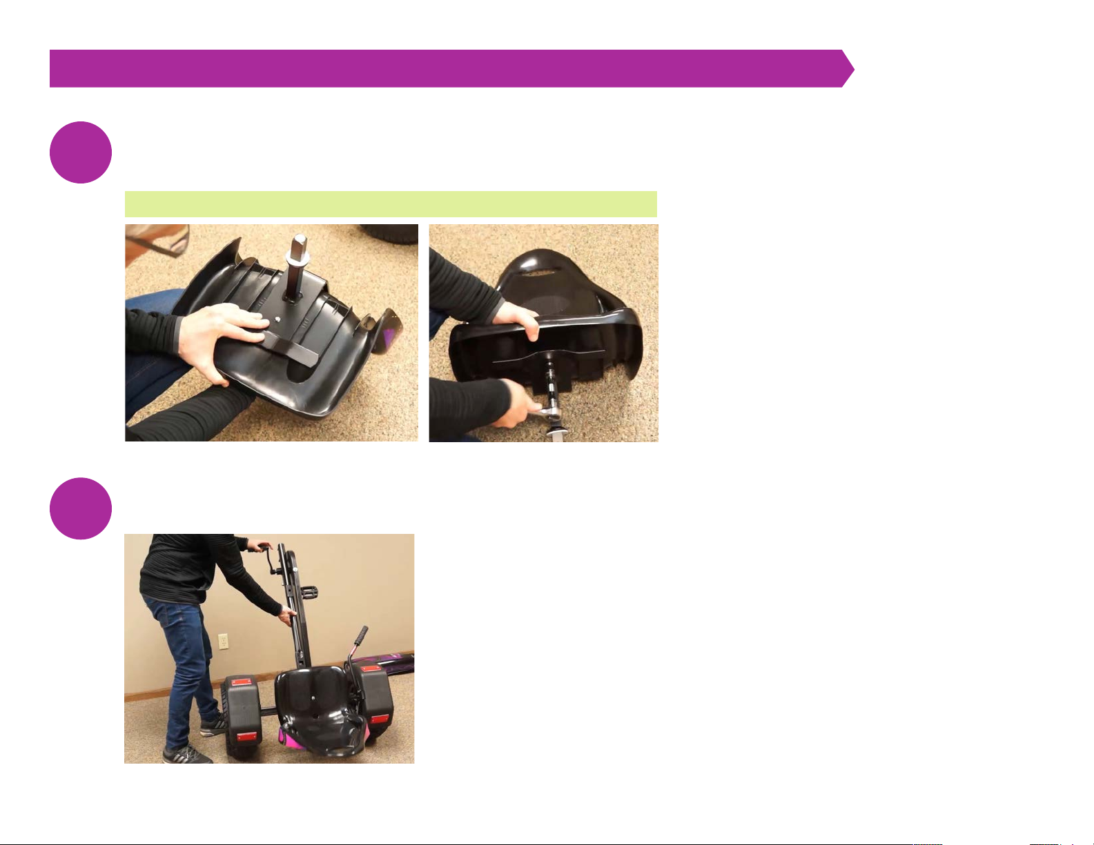
Assemble the seat: Slide the metal seat frame into the slot on the back of the plastic seat and line up the
hole on the seat frame with the hole on the seat. Insert the seat bolt (D in hardware) through the plastic seat,
then attach the washer and nut on the back of the metal seat frame using a 13mm wrench or socket.
Place the seat in the last seat position and stand the kart up on its end, resting on the seat back.
7
8
VIDEO 3:18 ASSEMBLE THE SEAT
[ 7 ] Fatal Vision® Roadster Assembly Instructions and Maintenance Guide | © Innocorp, ltd. www.fatalvision.com
FATAL VISION® ROADSTER STEP BY STEP ASSEMBLY INSTRUCTIONS [ SINGLE SEATER ]
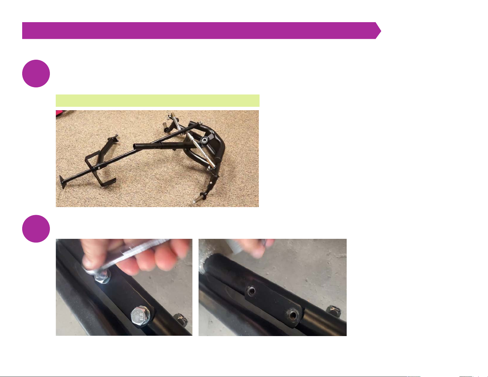
Remove all pre-assembled hardware: 2 bolt assemblies from the front axles (17mm socket), 1 bolt from the end
of the steering shaft (13mm wrench), 1 screw from the front of the spoiler mount bracket (Philips screwdriver),
and 1 bolt from the steering wheel mounting plate (13mm socket). Be careful to set and remember where each
bolt belongs.
Use a 17mm socket or wrench and remove the 2 existing bolts/washers by the chain drive on the rear assembly.
9
10
VIDEO 4:17 REMOVE ALL PRE-ASSEMBLED HARDWARE
[ 8 ] Fatal Vision® Roadster Assembly Instructions and Maintenance Guide | © Innocorp, ltd. www.fatalvision.com
FATAL VISION® ROADSTER STEP BY STEP ASSEMBLY INSTRUCTIONS [ SINGLE SEATER ]
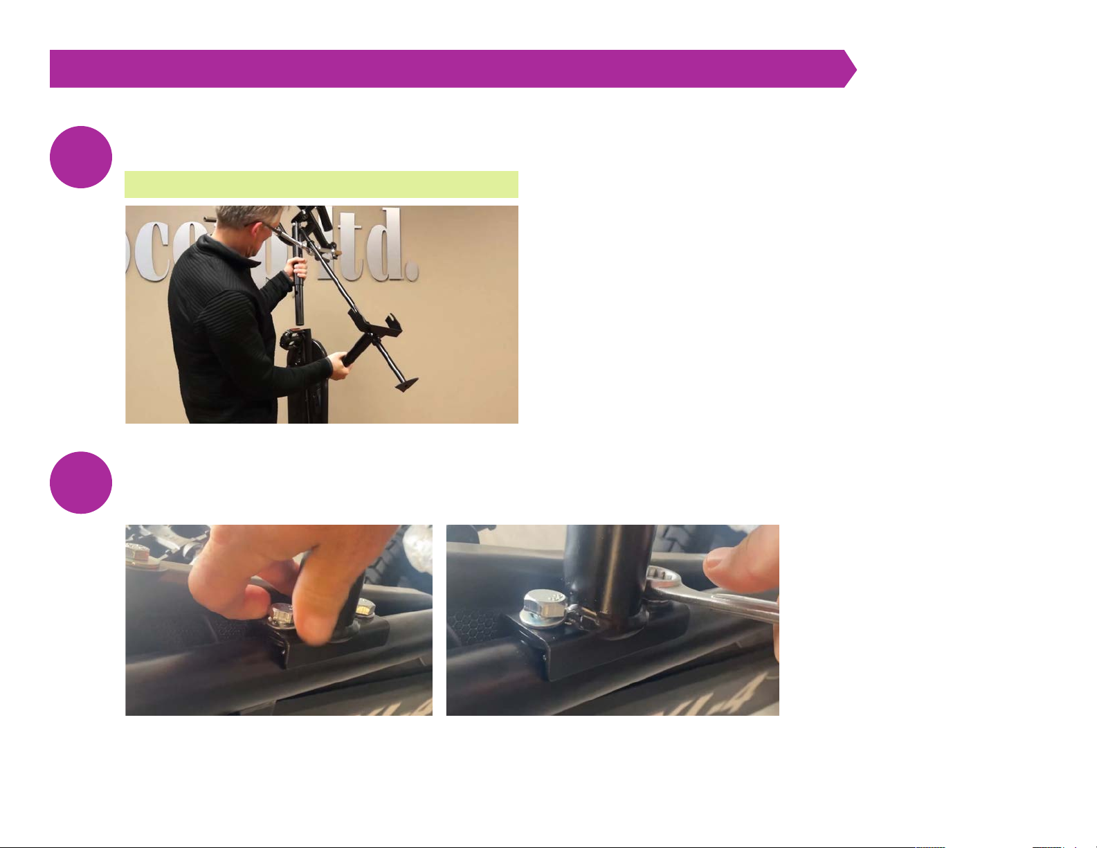
Slide the front assembly into the tube of the rear assembly.
Use a 17mm socket or wrench to replace the 2 bolts/washers by the chain drive on the rear assembly to
attach the steering column brace. Do not tighten the front bolt all the way yet. This maneuverability is
needed to shift and position the steering rod next.
11
12
VIDEO 5:45 ATTACH FRONT ASSEMBLY ONTO REAR ASSEMBLY
[ 9 ] Fatal Vision® Roadster Assembly Instructions and Maintenance Guide | © Innocorp, ltd. www.fatalvision.com
FATAL VISION® ROADSTER STEP BY STEP ASSEMBLY INSTRUCTIONS [ SINGLE SEATER ]
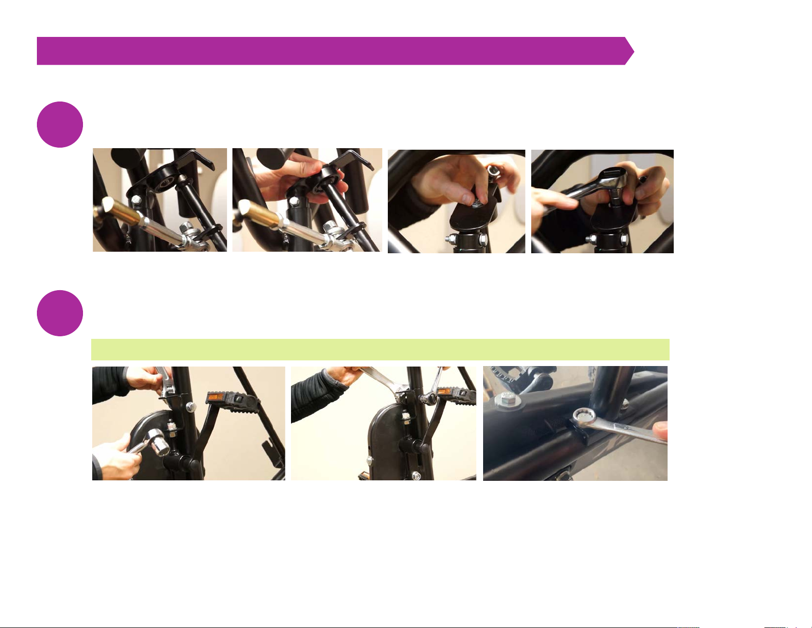
Install the end connection bolt and washer onto the end of the steering rod and tighten using a 13mm socket.
Install the frame connection bolt, washers, and nut assembly. (B in hardware) Tighten using 19mm wrenches/sockets.
Afterward, finish tightening the bolts to secure the steering column brace.
13
14
VIDEO 7:06 INSTALL FRAME CONNECTION BOLT
[ 10 ] Fatal Vision® Roadster Assembly Instructions and Maintenance Guide | © Innocorp, ltd. www.fatalvision.com
FATAL VISION® ROADSTER STEP BY STEP ASSEMBLY INSTRUCTIONS [ SINGLE SEATER ]
Attach both front wheels and tighten using a 17mm socket. The air intake valve stems should face inward while
attaching the wheels.
Place the spoiler mounting brackets (C in hardware) on the frame metal support brackets.
15
16
VIDEO 8:00 ATTACH FRONT WHEELS
VIDEO 9:34 INSTALL FRONT SPOILER


