
Premier Mounts Convergent Series User manual

9500255 v1.2
publ. 07/21/20
SERIES: SAM IF(H)
INSTALLATION GUIDE
Convergent Series Video Wall Mount
For Samsung IF(H) LED Cabinets

Page 2
Solid or continuous plywood backing with a min of 3/4” thickness, sound and secured
to handle the total combined weight of the mount and LED cabinets.
±1/2” or 1” max adjustment range
for flatness of wall, over the entire
wall surface
±1/4” Post-level adjustment from
each mounting point
CAUTION STATEMENTS
WALL REQUIREMENTS:
MAX FLATNESS ADJUSTMENT MAX POST-LEVEL ADJUSTMENT
Tools for Installation:
00.0 o
Spool of
colored strings
Anti-Static
Gloves
LASER
1. READ ALL STEPS WITHIN THIS MANUAL BEFORE INSTALLING THE MOUNT. SAMSUNG IF(H) LED
SERIES INSTALLATION GUIDE MUST BE READ IN CONJUNCTION FOR SUCCESSFUL
INSTALLATION. ANY QUESTIONS? CALL PREMIER MOUNTS.
2. INSTALLATION MUST MEETS THE REQUIREMENTS APPROVED BY THE STRUCTURAL ENGINEER.
3. FRAME MUST BE PLUMBED, SQUARED, LEVELED, X, Y, AND Z ALIGNED PRIOR TO INSTALLATION OF
ANY DISPLAYS.
4. ALL LED CABINETS MUST BE POWER ON TESTED PRIOR TO ANY INSTALLATION.
5. PREMIER MOUNTS RECOMMENDS THE HANDLING LED CABINETS BY AN INDUSTRY QUALIFIED
PROFESSIONAL.
6. PREMIER MOUNTS IS NOT RESPONSIBLE FOR DEFECTS, MISUSE, OR IMPROPER HANDLING OF THE
LED CABINETS.
Installation Guide
- SAMSUNG IF (H)

Page 3
VIDEO WALL DIMENSIONS AND MOUNTING LOCATIONS
OVERALL WIDTH
Available Rail
Size X
Y
AFF
LASER
LEVEL
OVERALL
HEIGHT
Available
Size
Imperial
(Inches)
Metric
(Milimeters)
X2 Wide 37.77 959.4
3 Wide 56.67 1439.2
Y
1 High 21.23 539.3
2 High 42.49 1079.3
3 High 63.75 1619.3
The overall dimensions of any video wall array can be
calculated by using the table within this page.
The desired array size is a combination of available sizes.
Add the available sizes together to nd the overall width or
height of a given array.
For modular conguration, any combination of the rails
does not aect the overall dimension of the mount.
Example: an 4X4 is 75.56” x 85.01”, and
8X8 is 151.12” x 170.02”.
Installation Guide
SAMSUNG IF (H) -
Page 4
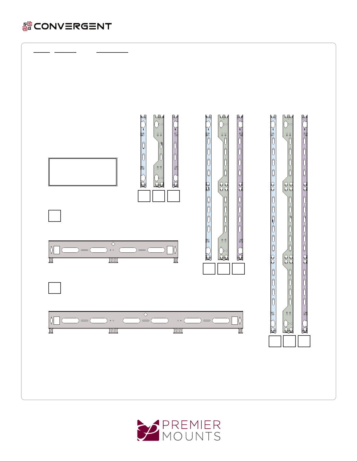
6 4000-300-221-LX Vertical Right End Rail 2V
7 4000-300-222-LX Vertical Center Rail 2V
8 4000-300-223-LX Vertical Left End Rail 2V
9 4000-300-231-LX Vertical Right End Rail 3V
10 4000-300-232-LX Vertical Center Rail 3V
11 4000-300-233-LX Vertical Left End Rail 3V
ITEM #. PART NO. DESCRIPTION
1 4000-300-212-LX Horizontal Rail 2H
2 4000-300-213-LX Horizontal Rail 3H
3 4000-300-218-LX Vertical Right End Rail 1V
4 4000-300-219-LX Vertical Center Rail 1V
5 4000-300-220-LX Vertical Left End Rail 1V
2 WIDE
1 HIGH 2 HIGH 3 HIGH
3 WIDE
1
7
10
6
9
5
8
11
2
34
AVAILABLE
SIZES
Installation Guide
- SAMSUNG IF (H)

Page 5
PRE-INSTALLATION
Floating Adjustment Assembly
(or “Floaters”)
Floaters must be install on every end of each Horizontal Rail brackets. If another
rail brackets are used to extend the horizontal width, only one floater is required in
the middle on either side. Both side can be used if neccessary.
1. Assemble the oating adjustment assemble shown above at every mounting point location, indicated by
the rectangular v-groove cutout.
2. Loosely fasten the M6 x 35mm Socket Head to the bracket. The tip of the screw should NOT touch the
surface of the horizontal bracket to allow adjustments at post installation.
Nylon Washer
Steel Washer
M5 x 10mm
Comb Screw
M6 x 35mm
Socket Screw
±1/4” adjustment from
neutral position
INSTALL NOT USEDREQUIRED REQUIRED
Rail 1 Rail 2
To keep the flange
straight at all times.
DO NOT REMOVE.
Installation Guide
SAMSUNG IF (H) -

Page 6
All configurations require the left and right vertical rail brackets mounted at the ends of the entire array
with the “center” verticals placed continuously in between. See page 8 for additional detail.
MOUNTING SURFACE INFORMATION
ASSEMBLE THE FRAME
1/8” min. gap
WALL REQUIREMENT:
A solid or continuous
plywood backing wall with
min. of 3/4” thickness.
1/2”-13 x 1.5”
Thru Bolt
Wall Anchor
Plate
1/4” x 5” Hex
Lag w/ washer
Vertical Rail
Horizontal
Rail
(4) M5 x 8mm
Flat Head per
Vertical Rail
(center)
Vertical Rail
(Left)
Vertical Rail
(Right)
Installation Guide
- SAMSUNG IF (H)
1
2

Page 7
1. Install a few support screws to hold the mount roughly near the desired location.
2. Place a level on top of the mount and readjust the support screws if necessary.
3. Secure the rst mounting location by sliding a Wall Anchor Plate behind the mount and fasten using
1/4” x 5” Hex Lag and 1/4” Washer.
4. Maintain a 1/8” minimum gap from the anchor plate and rail bracket when anchoring.
5. Install the remaining upper mounting locations while keeping the mount leveled.
Support Screws
(temporary)
Do Not Anchor Prior to
Final Mounting Location
LASER / LEVEL
00.0 o
Support Screw
(optional)
Bolted Bolted
Install a few support screws (commercially available hardware) to temporary hold the lower portion of
the mount. Do not bolt the frame at circled mounting point location. Adjust or nudge the frame left or
right until the mount is squared.
Installation is not finished within this step. The frame must be fully squared and
leveled prior to final mounting location. See step 9-10 for additional detail.
1” (25.5mm) cutout
for hanging the rail
bracket temporary
Installation Guide
SAMSUNG IF (H) -
3
4

Page 8
Multiple Unit Conguration
1. Hang and position the second Horizontal Rail side by side.
2. Place a support screw while maintaining a leveled horizontal rail to temporary hold in place.
3. Install (2) Attachment Plate and fasten together using (4) M5 x 8mm Flat Head Screw for each rail.
4. Install the remaining Vertical Rails (center) using (4) M5 x 8mm Flat Head Screw.
5. Install the lower section of the mount as the steps above.
To extend the width of the unit, follow the steps below.
Extend Horizontally
Horizontal Rail
(1st unit)
Horizontal Rail
(2nd unit)
00.0 o
Attachment
Plate
M5 x 8mm Flat
Head Screw
Vertical Rail
(center)
Figure 1
Figure 2
LASER / LEVEL
the seam between
two units
Installation Guide
- SAMSUNG IF (H)
5

Page 9
Extend Vertically
Multiple Unit Conguration
1. Place the rail brackets directly above or below the another rail brackets as shown.
2. Use the Attachment Plates to unite the two rail brackets together. Fasten using (2)
M5 x 8mm Flat Head Screw per.
3. Between the two units, only a single row of horizontal rail brackets are used for
standard application.
To extend the height of the unit, follow the steps below.
One row of horizontal rail brackets
on either side for standard (non-
mosaic) application.
No additional
Horizontal Rail
No additional
Horizontal Rail
Installation Guide
SAMSUNG IF (H) -
6

Page 10
Inspect each bracket using
a Square and Level tool.
LASER / LEVEL
SQUARE AND LEVEL
00.0
o
Ø 0.28” hole
M5 x 0.8mm
tapped hole
Notes: Finetuning holes available at various location for
all rail brackets. Brackets shown for reference only.
FINETUNE THE RAIL FOR FLATNESS
1. Install wherever possible.
2. Use drywall or wood screws to pull the brackets towards the wall.
3. Use supplied M5 x 20mm Pan screw to push the brackets against the wall.
Towards
the wall
Against
the wall
Bowing
Rail
Z
Y
Flat Wall
Finetuning holes for reference
Installation Guide
- SAMSUNG IF (H)
7
8
Other manuals for Convergent Series
2
Table of contents






