
Precision matthews PM-1236T User manual

1 Copyright © 2021 Quality Machine Tools, LLCPM-1340GT v8 2021-04
PM-1236T/1340GT Lathes
Model PM-1340GT Shown Above
Model PM-1236T and PM-1340GT Lathes
This manual was written for the PM-1340GT. The PM-1236T lathe,
also manufactured in Taiwan, is identical in all respects other than
overall weight, motor, bed length, and spindle height over the bed.
Items specic to the PM-1236T are noted in this color, italic.

2 Copyright © 2021 Quality Machine Tools, LLCPM-1340GT v8 2021-04
PM-1340GT
This manual contains essential safety advice on the proper setup, operation, maintenance, and service of
the PM-1340GT lathe. Failure to read, understand and follow the manual may result in property damage
or serious personal injury.
There are many alternative ways to install and use a lathe. As the owner of the lathe you are solely
responsible for its proper installation and safe use. Consider the material contained in this manual to
be advisory only. Quality Machine Tools, LLC cannot be held liable for injury or property damage during
installation or use, or from negligence, improper training, machine modications or misuse.
This manual describes PM-1340GT machines as shipped from May 2016. There may be detail
dierences between your specic machine and the information given here (with little or no impact
on functionality). Please email us if you have questions about any aspect of the manual or your
machine (see our website www.precisionmatthews.com for support addresses). Your feedback is
welcomed!
FAQ
POWER light o (left)?
240 Vac power connected?
Overload circuit breaker tripped?
E-STOP button (right) pushed in?
(will pop out when rotated)
5A (low-voltage) fuse blown?
My lathe doesn’t
run at all
By design it should NOT run if
the Motor Control switch was
UP or DOWN when power is
connected.
Electrical schematic, Section 5:
move the Motor Control switch
to neutral, mid travel, to energize
the 24Vdc relay, thus restoring
normal conditions.
The motor didn’t run when
power was connected
Copyright © 2021 Quality Machine Tools, LLC
This material was originated by Precision Matthews. No portion of
the manual may be reproduced or distributed in any form without
the written approval of Quality Machine Tools, LLC.
3 Copyright © 2021 Quality Machine Tools, LLCPM-1340GT v8 2021-04
Section 1 INSTALLATION
THESE ARE THE MAIN POINTS TO WATCH OUT FOR!
But read the following pages for more information
• Handling the lathe is at least a two-man job.
• Lifting gear – sling, hoist or forklift – must be rated for at least 1 ton.
• Working location of the mill must allow space for removal of the belt cover at left, also
access to the coolant system (if installed) and the electrical box at the back of the head-
stock.
• Power requirement is 220 - 240V, 60Hz, 1φ (spindle motor 12A full load), or 3φ (9A full
load). Single phase only, 10A full load
• Extension cord not recommended; if no alternative, use 12 AWG not longer than 20 ft.
• Before connecting power check the following:
1. Machine on a rm footing, adequately secured to its stand.
2. Chuck camlocks tight, no wrench left in chuck.
3. Motor control switch OFF, mid-travel (Figure 1-6).
4. Carriage and cross slide approx. mid-travel, power feed disengaged (Figure 1-7).
5. Headstock gear selectors set for the lowest spindle speed (Figure 1-5).
1. Prepare the working location for the stand. If you in-
tend to use an engine hoist, there must be room for
the hoist, Figure 1-3. If not, a forklift and slings may
be a better option. If only an engine hoist is avail-
able, with limited space either side, the machine can
be fully assembled on a pair of 4-wheel dollies, then
rolled to its nal position. The assembly can then
be raised by screw jacks or other means to free the
dollies.
2. Position the LH and RH stand cabinets 40-1/4 inch-
es apart in the lathe’s nal location. Install the front
panel between the two stand cabinets.
3. Highly recommended!
Install leveling mounts rated for 250 lb each at the
corners of the stand cabinets. Depending on stud
size drill four 3/8" or 1/2" holes on the underside of
each stand. Alternatively, plan on leveling the ma-
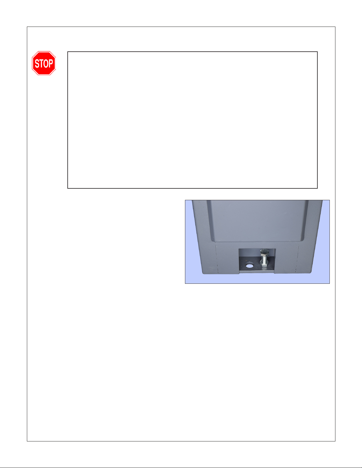
chine with the supplied screws front and back, Fig-
ure 1-1, then pack metal shims under the cabinet
rims for a rock-solid installation.
4. Position the chip tray on the stands, aligning the
SETTING UP THE LATHE
The PM-1340GT is shipped in three packing cases, one
for the machine/chip tray/front panel/back splash, one
each for the left and right hand stand cabinets. The fol-
lowing procedure makes use of an engine hoist, mini-
mum weight rating 1 ton.
Figure 1-1 Supplied leveling screws
6 holes for mounting bolts with the corresponding
threaded holes on top of the cabinets. Optional:
apply double-sided adhesive tape to the bearing
surfaces on top of the cabinets. This will keep the
through holes aligned, making installation much
easier. For a solid installation — no rocking — use
very thin non-foam tape.
5. Remove the packing case from the pallet, then un-
bolt the machine from the pallet.
6. Balancing the lathe on a single-point hoist may take
a few tries. Run the carriage and tailstock down to
the headstock as far as possible without interfering
with the slings and stretchers, see the next step.
6. Run two 1000 lb slings under the lathe bed and up
to the hoist hook, with stretchers above and below

4 Copyright © 2021 Quality Machine Tools, LLCPM-1340GT v8 2021-04
Figure 1-2 Installation using an engine hoist
the bed to keep the slings outboard of the lead-
screw, feed shaft and motor control rod to avoid
damage to those components, Figure 1-2. Use 3/4"
plywood, 10" long for the stretcher under the bed
(thicker material will prevent the lathe from seating
properly on the chip tray). The upper stretchers can
be 10" lengths of 2x4 or other rigid material. For
easier alignment on the chip tray, tap wooden dow-
els into the holes at the tail stock end of the lathe
bed (not shown in Figure 1-2).
7. Slowly lift the lathe, controlling any tendency for it to
swing as it clears the pallet.
8. Roll the lathe into position, then hover it an inch or
so over the chip tray. This will allow you to mark the
perimeters of the lathe bed pedestals for the pur-
pose of caulking (optional — applies only if continu-
ous coolant ow is anticipated).
9. (Optional) Apply a thick bead of silicone caulk just
inside the marked perimeters on the tray.
10. Lower the lathe onto the chip tray, making sure that
LEVELING
Make sure the lathe is in its permanent location. The
leveling procedure ensures that the lathe bed is in the
same state as it was when the lathe was checked for ac-
curacy in manufacture — level from end to end along the
bed, and from front to back. In other words, no warping.
Make sure all leveling mounts under the cabinets are
properly weight bearing, rmly in contact with the oor.
Check and adjust level from end to end using a “preci-
sion machinist’s level”, if available. If not, use the most
reliable level on hand. Check and adjust level front-to-
back across the bed using a matched pair of spacer
blocks to clear the Vee tenons on the bed ways. The
blocks need to be ground, or otherwise accurately di-
mensioned. Alternatively, check for level on the ground
surface of the cross slide as the carriage is traversed
from end to end.
CONNECTING POWER
As shipped. the PM-1340GT is set for 220 V. If your
supply is nominally 240 V, it may be desirable to alter
CLEANUP
Metal surfaces may be protected by thick grease and/
or paper. Carefully remove these using a plastic paint
scraper, disposable rags and a light oil such as WD-40.
its six mounting holes are properly aligned. Excess
caulk squeezed out by the pedestals will form a
coolant-proof seal.
11. Install the six supplied M12 x 40 hex head bolts
with washers. Fully tighten the bolts. Re-check the
caulking on both pedestals.
12. Install the backsplash on the lathe.
Figure 1-3 Installation using a forklift

5 Copyright © 2021 Quality Machine Tools, LLCPM-1340GT v8 2021-04
Figure 1-4 Electrical box inputs/outputs
This conguration may vary depending on installed options, etc.
Figure 1-5 Motor control switches
connections to the 24V transformer in the electrical box.
If the lathe did not come with a pre-installed power cord,
connect to the power source using 12 AWG (minimum)
3-wire cord through a strain relief bushing sized for the
electrical box ports. Depending on installed options and
other factors, the entry point shown in Figure 1-4 may
not be available.
Spindle rotation
The motor control switches, Figure 1-5, are usually wired
so that the spindle turns counter-clockwise (viewed at
the chuck) when the motor control lever is down, see
Figure 1-7.
Some users prefer the lathe to run clockwise when the
control lever is down, in which case it may be necessary
to swap the wires to the motor control switches, Figure
1-5.
Alternatively, on a 3-phase installation, swap two of the
phases R, S or T on the terminal block. This will not af-
fect the coolant pump motor (if tted), which is single
phase.

6 Copyright © 2021 Quality Machine Tools, LLCPM-1340GT v8 2021-04
8. Check that there are no clamps or locks on moving
parts.
9. Set the carriage and cross slide to approximate
mid-travel.
10. Make certain that the motor control switch is set to
OFF, mid-travel, Figure 1-6.
11. Make certain that the power feed lever and lead-
screw split-nut lever are disengaged, Figure 1-7.
When both are disengaged, the cross slide and
carriage handwheels should turn freely.
11. Connect power. The power lamp (far left of the
orange color E-Stop button) should light, unless the
E-Stop button has been pushed in (it should pop
out when twisted clockwise).
12. Shift the motor control lever DOWN. The spindle
should turn forward, counter clockwise, viewed at
the chuck (nose) end.
INITIAL CHECKS
Read Section 3 if unsure about any item in the
following.
Do not connect power at this stage
1. Check oil level (sight glasses) in the headstock
and the apron. See Section 4, Figure 4-2.
2. Inject a small amount of oil into the gearbox oil
gallery, making certain that all seep holes in the
gallery are covered, Figure 4-3.
3. Lubricate the leadscrew and feed shaft oilers at the
tailstock end.
4. Remove the belt cover left of the headstock. Make
sure the belt is properly tensioned and set for the
low speed range. If not, re-position the belt, Figure
3-3.
5. Replace the belt cover.
6. If a chuck or faceplate is installed check tightness
of the three Camlocks on the spindle nose, Figure
3-27.
7. Set the spindle speed gear levers to L-2, Figures
1-5 and 3-4. With the drive belt set for low speed
this will give a speed of 90 rpm. Do not change
spindle speed, feed speed or feed direction
when the motor is running.
Figure 1-6 Headstock controls
Figure 1-7 Forward/Reverse motor control
Mid-travel OFF, Down FORWARD, Up REVERSE
Figure 1-8 Feed control levers

7Copyright © 2021 Quality Machine Tools, LLCPM-1340GT v8 2021-04
13. Check the emergency function by pressing the
E-Stop button. The motor should stop. If this
doesn’t happen, the E-stop function is defec-
tive, and needs attention.
14. Reset (twist) the E-Stop button to restore power.
15. Return the motor control lever to OFF, mid-travel.
The motor should stop.
16. Shift the motor control lever UP. The spindle should
reverse, clockwise rotation, viewed at the chuck
(nose) end.
OPTIONAL TEST RUN PROCEDURE
Run the spindle for a few minutes, forward and reverse,
at each of the 6 speeds available with the low speed Vee
belt conguration, then repeat with the Vee belt changed
to high speed.
Note: In initial tests the carriage and cross slide should
rst be exercised manually, then under power.
After the initial test run, with 10 additional hours of ma-
chine time, the headstock should be drained and relled.
ALIGNING THE LATHE
The most important attribute of a properly set up lathe
is its ability to “machine parallel”, to cut a cylinder of uni-
form diameter over its entire length. In other words, no
taper.
Leveling of the lathe is a part of this, see earlier in
this section. Equally important is the alignment of the
center-to-center axis with the lathe bed, as seen from
above. [Vertical alignment is nowhere near as critical,
rarely a cause of taper unless the lathe is damaged or
badly worn.] For more information see the nal pages of
Section 4, Servicing the Lathe.

8 Copyright © 2021 Quality Machine Tools, LLCPM-1340GT v8 2021-04
Section 2 FEATURES & SPECIFICATIONS
MODEL PM-1340GT LATHE (PM-1236T)
General information
The PM-1340GT is a high quality gap-bed lathe designed for day-in, day-out use in the model shop or tool room.
Distance between centers is 40 in., swing over the bed 13 in. (19-1/8 in. with the gap insert removed). With an all-up
weight of over 1300 lb, choice of precision chucks, plus a range of speeds from 90 to 1800 rpm, the PM-1340GT
is one of the most versatile small machines available. The spindle nose is D1-4 Camlock. A quick-change carriage
feed gearbox provides a full range of leadscrew ratios for U.S. (TPI) screw cutting, without external gear swapping,
together with an independent power feed for both saddle and cross slide. The power feed shaft is driven through a
friction clutch that allows the saddle to be stopped with micrometer precision at any point along the bed. A coolant
system and taper turning attachment are two of the many options available for the PM-1340GT.
The spindle has a 1-9/16 in. clearance bore and MT5 internal taper. It runs in tapered-roller bearings, and is driven
by a 9-speed gearbox, coupled by Vee-belt to a 2 HP (1500 W) 220-240 Vac three-phase motor (single-phase op-
tional). Two-step Vee pulleys provide a choice of high and low speed ranges, giving a total of 12 spindle speeds — 6
high range plus 6 low range.
PM-1340GT (PM-1236T) Floor plan: dimensions approximate (not to scale)
65-1/2"

9Copyright © 2021 Quality Machine Tools, LLCPM-1340GT v8 2021-04
Dimensions, approximate overall Including stand: Width 69-1/4 in. (65-1/2 in.), Height 48-1/2 in.
Depth 22 in. at chip tray, add 5 in. for cross slide
Weight (lathe, excluding stand), net 1100 lb (850 lb)
Welded steel stand, net 250 lb
Cast iron stand, net 500 lb
Power requirement (two options) 1. 220 - 240Vac, 60 Hz, 1Ø, 12A full load
2. 220 - 240Vac, 60 Hz, 3Ø, 9A full load
Motor type TEFC, 1.5 kW (2 HP), 1725 rpm
1.5 HP, 1Ø only, 10A full load
Work envelope
Gap insert length 7-1/2 in.
Distance between centers 40 in. 36 in.
Swing over gap 19-1/8 in. 18 in. diameter
Swing over bed 13 in. 12 in. diameter
Swing over cross slide 6-1/2 in. 6 in. diameter
Cross-slide travel 6-3/4 in.
Compound (top slide) travel 3-1/2 in.
Center rest (steady rest) capacity 2-1/2 in. diameter
Follower rest capacity 1-1/2 in. diameter
Drive system
High/Low belt drive with 6-speed gearbox
Low range, rpm 90, 135, 205, 205, 308, 475
High range, rpm 335, 505, 770, 780, 1160, 1800
Carriage drive, thread cutting Leadscrew 8 tpi
Inch threads Choice of 40, from 4 to 112 TPI
Metric threads Choice of 24, from 0.25 to 7.5 mm pitch
Carriage drive, turning operations Choice of feed rates from 0.0027 to 0.08 in./spindle rev
Cross slide drive Choice of feed rates from 0.0015 to 0.04 in./spindle rev
Spindle
Chuck/faceplate attachment D1-4 Camlock
Internal taper MT5
Spindle bore 1-9/16 in.
Spindle length, chuck removed 13-3/4” (add approx 3-1/2 in. for 3-jaw chuck)
Tailstock
Internal taper MT3
Quill travel 4 in.
PM-1340GT (PM-1236T) SPECIFICATIONS

10 Copyright © 2021 Quality Machine Tools, LLCPM-1340GT v8 2021-04
Everyday precautions
• This machine is intended for use by experienced users familiar with met-
al-working hazards.
• Untrained or unsupervised operators risk serious injury.
• Wear ANSI-approved full-face or eye protection at all times when using the
machine (everyday eyeglasses are not reliable protection against ying parti-
cles).
• Wear proper apparel and non-slip footwear – be sure to prevent hair, cloth-
ing or jewelry from becoming entangled in moving parts. Gloves – including
tight-tting disposables – can be hazardous!
• Be sure the work area is properly lit.
• Never leave chuck keys, wrenches or other loose tools on the machine.
• Be sure the workpiece, toolholder(s) and machine ways are secure before
commencing operations.
• Use moderation: light cuts, low spindle speeds and slow table motion give
better, safer results than “hogging”.
• Don’t try to stop a moving spindle by hand – allow it to stop on its own.
• Disconnect 220 Vac power from the mill before maintenance operations such
as oiling or adjustments.
• Maintain the machine with care – check lubrication and adjustments daily
before use.
• Clean the machine routinely – remove chips by brush or vacuum, not com-
pressed air (which can force debris into the ways).
No list of precautions can cover everything.
You cannot be too careful!
This manual suits for next models
1
Table of contents
Other Precision matthews Lathe manuals

Precision matthews
Precision matthews PM-1440BV User manual

Precision matthews
Precision matthews PM-1022V User manual

Precision matthews
Precision matthews PM-1228VF-LB User manual

Precision matthews
Precision matthews PM-1127VFI-LB Installation guide

Precision matthews
Precision matthews PM-1440GS User manual

Precision matthews
Precision matthews PM-1440-2SM User manual

Precision matthews
Precision matthews PM-1440E-LB Installation guide

Precision matthews
Precision matthews PM-1127VF-LB User manual

Precision matthews
Precision matthews PM-1440GT User manual

Precision matthews
Precision matthews PM-1236 User manual


