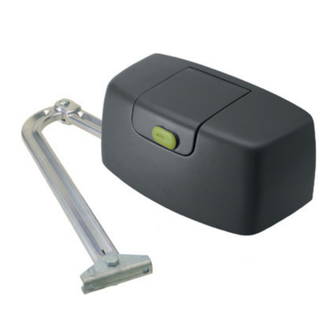
PPA DZ 1500 User manual

DZ PREDIAL
DZ CONDOMINIUM
DZ 1500
Technical Manual


INDEX
1 GATE OPERATOR CLASSIFICATIONS ....................................... 4
2 SAFETY ACCESSORY SELECTION ............................................. 4
3 ENTRAPMENT PROTECTION TYPES......................................... 4
4 IMPORTANT SAFETY INSTRUCTIONS..................................... 5
4.1 – Safety Installation Information ............................. 5
5 TECHNICAL SPECIFICATION....................................................... 6
6 REQUIRED TOOLS FOR INSTALLATION .................................. 7
7 ELECTRICAL INSTALLATION ....................................................... 7
8 PRECAUTIONS FOR ELECTRICAL INSTALLATION............... 8
9 INSTALLING AND FIXING THE OPERATOR ............................ 8
10 - LIMIT SWITCH INSTALLATION .................................................12
11 - INTRODUCTION: ELECTRONIC SYSTEM’S TECHNICAL
FEATURES ...............................................................................................13
12 - CONTROL BOARD........................................................................13
12.1 - Overview ..................................................................13
12.2 - Power Supply...........................................................14
12.3 - Induction Motor Connection .............................14
12.4 - ‘ENC’ encoder connection ...................................14
12.5 - ‘TRAVA’ Audio Alarm connection ......................15
12.6 - ‘LUZ’courtesy light connection.........................15
12.7 - ‘RX’ separated receiver connection ..................15
12.8 - ‘BOT’ pushbutton connection ............................15
12.9 - ‘HIB’ end-of-stroke reeds connection..............15
12.10 - ‘SCI’ connector.......................................................15
13 - ENTRAPMENT PROTECTION SYSTEMS.................................16
13.1 - Internal Entrapment Protection
System (Type A) ..................................................................16
13.2 - External Entrapment Protection
System (Type B1)................................................................16
13.3 - ‘FOT’ closing cycle photoelectric sensor ........17
13.4 - ‘FEC’ opening cycle photoelectric sensor ......17
13.5 - Miller Edge reexi Gard Connection ...............18
13.6 - ‘ABR’ audio alarm reset connection..................19
14 - FORCE ADJUSTMENT................................................................. 19
14.1 - ‘FOP’ High Speed Force Adjustment................19
14.2 - ‘FME’ Low Speed Force Adjustment.................20
15 - GATE SYSTEM LOGIC FUNCTION ...........................................20
15.1 - First operation after a frequency
inverter is installed on the operator (Gate travel
recognition)..........................................................................20
15.2 - From the second activation on, when the
control board is disconnected from the power
supply.....................................................................................20
16 - INVERTER PARAMETERS PROGRAMMING ..........................21
16.1 - Operator model selection...................................21
16.2 - JUMPER TST ..............................................................21
16.3 - Adjustment of other parameters......................21
17 - ERASING THE RECOGNIZED GATE TRAVEL .........................24
18 - APPLYING THE DEFAULT STANDARD SETTINGS ...............24
19 – ADDING A REMOTE CONTROL...............................................24
19.1 – Remote control functions ..................................24
19.2 - The remote control battery.................................25
20 - SELECTION OF RF RECEPTION PROTOCOL (CR/CF
JUMPER)..................................................................................................26
21 - ERASING ALL STORED REMOTE CONTROLS ......................26
22 - USER OPERATION........................................................................26
22.1 - Unlocking (manual release and
operation) .............................................................................27
23 - ACCESSORIES................................................................................27
23.1 - Garage Light.............................................................27
23.2 - Flashing lights .........................................................28
24 - EVENT / FAILURE INDICATION.................................................28
24.1 - Microcontroller functioning indication..........28
24.2 – Indication of over current or short
circuit on the motor .........................................................28
24.3 – Overheating indication.......................................28
24.4 – EEPROM fault indication.....................................28
24.5 – EEPROM invalid data indication.......................28
24.6 - Open end-of-stroke indication..........................29
24.7 - Close end-of-stroke indication..........................29
24.8 - Capacitor load indication.................................... 29
24.9 - Encoder Test.............................................................29
24.10 - Thermal Protection..............................................29
25 - MAINTENANCE.............................................................................29
26 - REPAIR PARTS................................................................................30

4
1 - GATE OPERATOR CLASSIFICATIONS
All gate operators can be divided into one of four classes depending on their design and usage. Install this gate operator only when the
operator is appropriate for the construction and usage class as dened below:
Class I Residential Vehicular Gate Operator
A vehicular gate operator intended for use in a home or for one to four single family dwellings with a common garage or parking area
associated with these dwellings.
Class II Commercial / General Access Vehicular Gate Operator
A vehicular gate operator intended for use in a commercial location or building such as a multi-family housing unit of ve or more
single family units, hotel, retail store or other building servicing the general public.
Class III Industrial / Limited Access Vehicular Gate Operator
A vehicular gate operator intended for use in an industrial location or building such as a factory or loading dock area or other location
not intended to service the general public.
Class IV Restricted Access Vehicular Gate Operator
A vehicular gate operator intended for use in a guarded industrial location or building such as an airport security area or other restricted
access locations not servicing the general public, in which unauthorized access is prevented via supervision by security personnel.
2 - SAFETY ACCESSORY SELECTION
All UL325 PPA compliant gate operators will accept external entrapment protection devices to protect people from motorized gate
systems. UL325 requires that the type of entrapment protection correctly matches each gate application.
This equipment must be installed with at least two entrapment protection means. Below are the types of entrapment protection
systems recognized by UL325 for use on this operator.
3 - ENTRAPMENT PROTECTION TYPES
Type A:
Inherent obstruction sensing system, self-contained within the operator. This system must sense and initiate the reverse of the gate
within two seconds of contact with a solid object.
Type B1:
Connections provided for a non-contact device, such as a photoelectric eye can be used as a secondary protection.
NOTE: UL requires that all installations must have warning signs placed in plain view on both sides of the gate to warn pedestrians of the danger of motorized
gate systems.
Approved Non-contact Devices (Type B1)
The following non-contact obstruction detection devices have been approved for use with this slide gate operator (or barrier gate
operator) as part of a UL325 compliant installation:
Edge Miller 4-wire pulsed (monitored) devices.

5
4 - IMPORTANT SAFETY INSTRUCTIONS
WARNING
This equipment is to be installed and serviced by a professional gate
operator technician only. It is important that the specialized installer
follow all instructions given in this manual.
To Reduce the Risk of Severe Injury or Death:
1. READ AND FOLLOW ALL INSTRUCTIONS
2. Never let children operate or play with door controls. Keep the remote control away from children.
3. Always keep people and objects away from the gate. NO ONE SHOULD CROSS THE PATH OF THE MOVING GATE.
4. Test the gate operator monthly. The gate MUST reverse on contact with a rigid object or stop when an object activates the non-
contact sensors. After adjusting the force or the limit of travel, retest the gate operator. Failure to adjust and retest the gate operator
properly can increase the risk of injury or death.
5. Use the emergency release only when the gate is not moving.
6. KEEP GATES PROPERLY MAINTAINED. Read the owner’s manual. Have a qualied service person make repairs to gate hardware.
7. The entrance is for vehicles only. Pedestrians must use separate entrance.
8. SAVE THESE INSTRUCTIONS.
4.1 – Safety Installation Information
1. Install the gate operator only when:
a) The operator is appropriate for the construction and the usage class of the gate.
b) All openings of a horizontal slide gate are guarded or screened from the bottom of the gate to a minimum of 6’ (1.83 m)
above the ground to prevent a 2 ¼” (6cm) diameter sphere from passing through the openings anywhere in the gate, and in
that portion of the adjacent fence that the gate covers in the open position.
c) All exposed pinch points are eliminated or guarded, and guarding is supplied for exposed rollers
2. The operator is intended for installation only on gates used for vehicles. Pedestrians must be supplied with a separate access
opening. The pedestrian access opening shall be designed to promote pedestrian usage. Locate the gate such that persons will
not come in contact with the vehicular gate during the entire path of travel of the vehicular gate.
3. The gate must be installed in a location so that enough clearance is supplied between the gate and adjacent structures when
opening and closing to reduce the risk of entrapment. Swinging gates shall not be open into public access areas.
4. The gate must be properly installed and work freely in both directions prior to the installation of the gate operator
5. Controls intended for user activation must be located at least six feet (6’) away from any moving part of the gate and where the
user is prevented from reaching over, under, around or through the gate to operate the controls. Outdoor or easily accessible
controls shall have a security feature to prevent unauthorized use.
6. The Reset switch must be located in the line-of-sight of the gate. Activation of the reset control shall not cause the operator to
start.

6
7. A minimum of two (2) WARNING SIGNS shall be installed, one on each side of the gate where easily visible.
8. For a gate operator utilizing a non-contact sensor:
a) Reference the owner’s manual regarding placement of non-contact sensor for each type of application.
b) Care shall be exercised to reduce the risk of nuisance tripping, such as when a vehicle trips the sensor while the gate is still
moving.
c) One or more non-contact sensors shall be located where the risk of entrapment or obstruction exists, such as the perimeter
reachable by a moving gate or barrier.
9. For a gate operator utilizing a contact sensor such as an edge sensor:
a) One or more contact sensors shall be located where the risk of entrapment or obstruction exists, such as the leading edge,
trailing edge and post mounted both inside and outside of a vehicular horizontal slide gate
b) One or more contact sensors shall be located at the bottom edge of a vehicular vertical lift gate.
c) A hard wired contact sensor such as the one that transmits radio frequency (RF) signals to the gate operator for entrapment
protection functions shall be located where the transmission of the signals are not obstructed or impeded by building structures,
natural landscaping or similar obstruction. A wireless contact sensor shall function under the intended end-use conditions.
d) One or more contact sensors shall be located on the inside and outside leading edge of a swing gate. Additionally, if the
bottom edge of a swing gate is greater than 6” (152 mm) above the ground at any point in its arc of travel, one or more contact
sensors shall be located on the bottom edge.
e) One or more contact sensors shall be located at the bottom edge of a vertical barrier (arm).
5 - TECHNICAL SPECIFICATION
Model DZ PREDIAL JET FLEX
60HZ U
DZ CONDOMINIUM
JET FLEX 60HZ U
DZ 1500 JET FLEX
60HZ (Z12) U
Class of Operation UL325 Class I, II, III, IV UL325 Class I, II, III, IV UL325 Class I, II, III, IV
Type of Gate Vehicular Slide Gates Vehicular Slide Gates Vehicular Slide Gates
Main AC Supply 120 Vac, 5A (max) 120 Vac, 5A (max) 120 Vac, 9A (max)
Nominal Frequency 60 Hz 60 Hz 60 Hz
Rated Power 350 W, 120 Vac 350 W, 120 Vac 700 W, 120 Vac
Maximum Gate Weight 1300 lbs 1500 lbs 2600 lbs
Maximum Gate Travel
Speed 1 ft/s 1 ft/s 1 ft/s
Maximum Gate Length 32 feet 32 feet 32 feet
Cycles 60 60 60
Operating Temperature -4º F to 122º F -4º F to 122º F -4º F to 122º F
Inherent Entrapment
Protection (Type A)
Dual – RPM (Encoder)
and Current Sense
Dual – RPM (Encoder)
and Current Sense
Dual – RPM (Encoder)
and Current Sense
External Entrapment
Protection (Type B1)
2 inputs for
photoelectric devices
2 inputs for
photoelectric devices
2 inputs for
photoelectric devices

7
6 - REQUIRED TOOLS FOR INSTALLATION
Below are some tools necessary to install the operator:
PLIERS
SAW
NUT DRIVER
SCREWDRIVER
FIXED WRENCH
STAIRS
SQUARE
DRILL
PENCIL
SANDER
WELDING MACHINE
HAMMER
LEVEL
MEASURING TAPE
7 - ELECTRICAL INSTALLATION
This equipment must be wired with 120V as specied in the table below (assuming max current consumption).
IMPORTANT
Be sure that the circuit breaker in the electrical panel is in the OFF
position before proceeding with the installation.
A separated power disconnect switch may be needed in your area.
Check your local building codes before installing this equipment.
The gate operator must be properly grounded, check your local
electrical codes before installing this equipment.
Install the earth ground rod as near as possible to the operator.
AC power
Wire Size (American Wire Gauge) / Max Distance in Feet
DZ PREDIAL DZ CONDOMINIUM DZ 1500
14 AWG 12 AWG 14 AWG 12 AWG 14 AWG 12 AWG
120 VAC Single Phase 115 182 115 182 64 101

8
8 - PRECAUTIONS FOR ELECTRICAL INSTALLATION
To avoid damage to wiring, it is important that all conduits are properly xed to the operator. The passage of the wiring must be made
through conduits, internally to oor base, ensuring that no wiring conductor is trapped or damaged.
A conduit of 3/4"in diameter must be installed between the power distribution box and the total disconnect device inside the concrete
base.
Install conduits for the 120 Vac.
Main power supply MUST run in separated conduits.
The conduit may be limited to 1/2 "in diameter for external devices like pushbuttons or sensors.
All conduits must be UL approved.
9 - INSTALLING AND FIXING THE OPERATOR
Equipment dimensions: Model DZ PREDIAL Models DZ CONDOMINIUM and DZ 1500
14.01 in
11.57 in 6.14 in
8.35 in
12.28 in
7.99 in
6.18 in
12.64 in

9
The perfect operation of this equipment depends on the instructions in this manual. To x the equipment, follow these steps:
Step 1: Make sure the oor is rm enough so it can be screwed the equipment so that it is on the level. If it not meet the requirement,
provide a concrete pad, following the guidelines below:
Step 2: The dimensions of the concrete pad shall be appropriate for the operator dimensions. The concrete pad shall be at a distance
of approximately 0.79 inches from the face of gate leaf.
Step 3: After meeting the conditions, open completely the gate and position the operator near the face of the gate leaf, following the
measure of 1.97 inches between the end of the gate leaf and operator.
9.84 in 11.81 in
5.90 in

10
Step 4: Make the pre-alignment from operator to the gate, positioning the rack on the gear and leaning the set the gate. Then, mark
the xing holes in the oor or concrete pad.
Step 5: Make the hole for xing, positioning of the aligned operator to the gate and enter the anchor bolts ½ "x 4" without tightening
them. Move the gate, check if it does not touch the operator over the course. If this occurs, back o the operator.
Step 6: With the unlocked operator, position the rack bar on the gear and aligned to the gate.
It is necessary to leave a clearance of approximately 0.08 inches between the tooth top of the gear and rack tooth bottom.
This manual suits for next models
6
Table of contents
Other PPA Gate Opener manuals

PPA
PPA PIVOTING User manual

PPA
PPA DZ RIO 350 JET FLEX User manual

PPA
PPA BV HOME Series User manual

PPA
PPA BV POTENZA PREDIAL CUSTOM User manual

PPA
PPA SK User manual

PPA
PPA DZ HUB User manual

PPA
PPA PIVO CONDOMINIUM INOX User manual

PPA
PPA SPIN User manual

PPA
PPA DZ BRUTALLE 3.0T JetFlex User manual

PPA
PPA TORE User manual