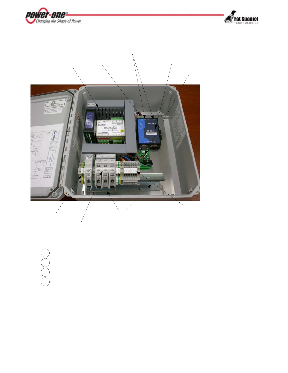
EquipmentandSupplies
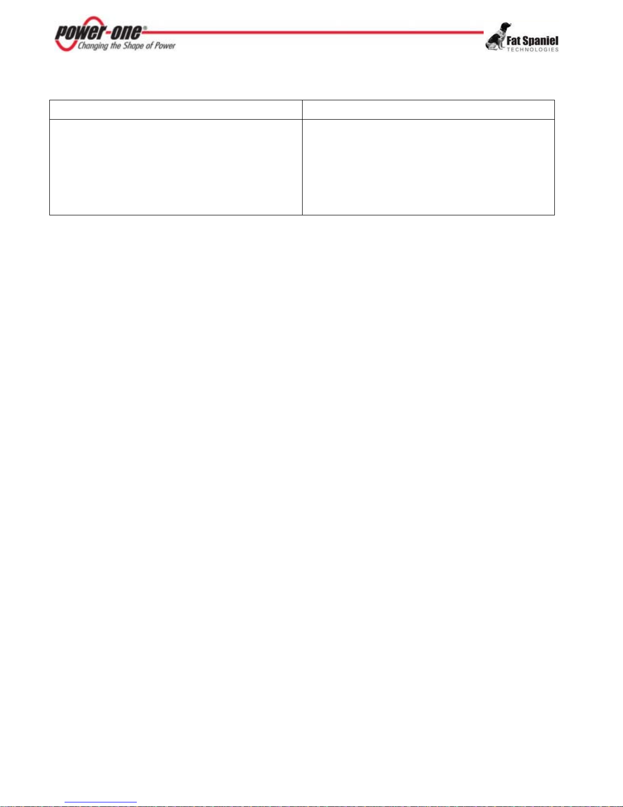
Wesupply:Yousupply:
AuroraUniversalSystem,whichincludes:
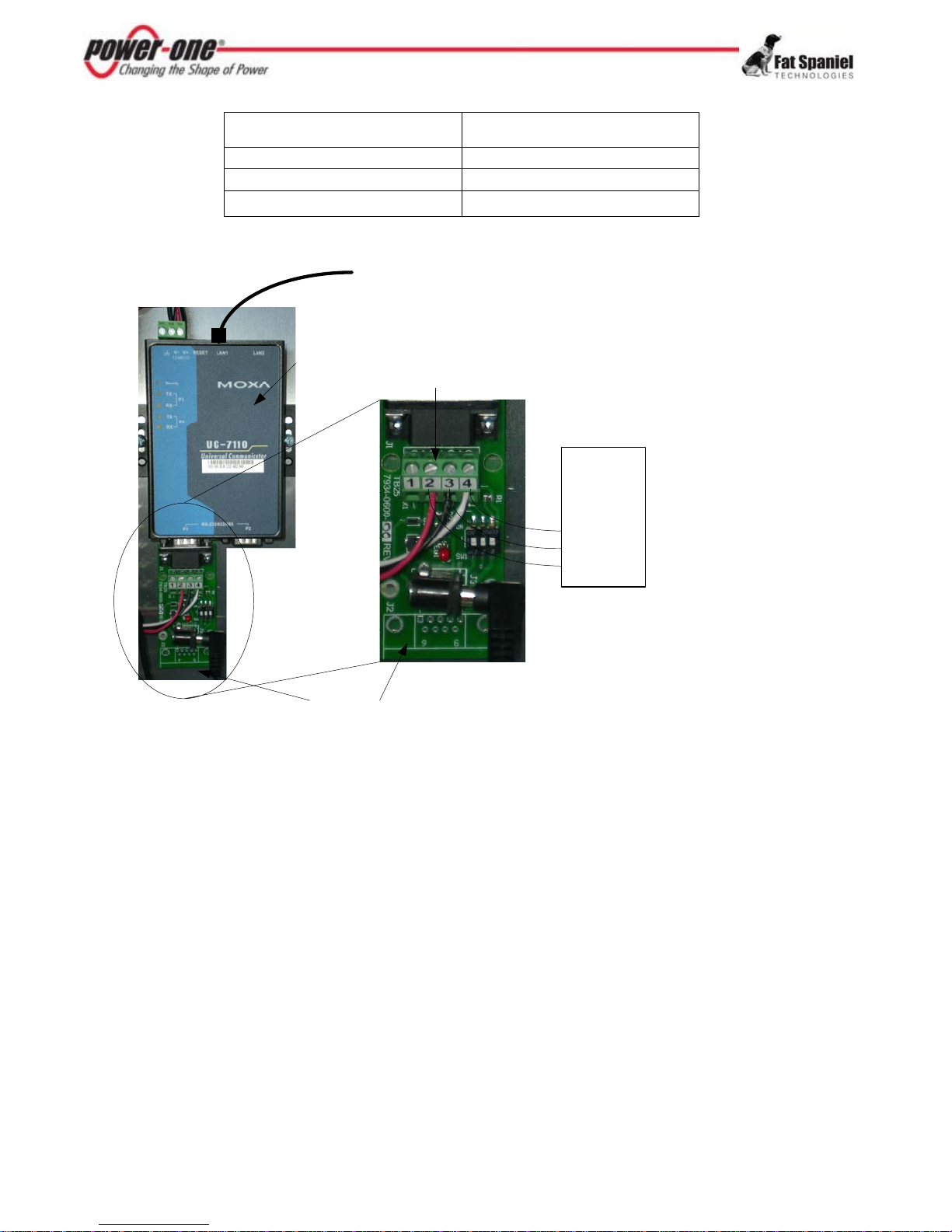
FatSpanielDataLoggerwithDB9adaptercard(s)
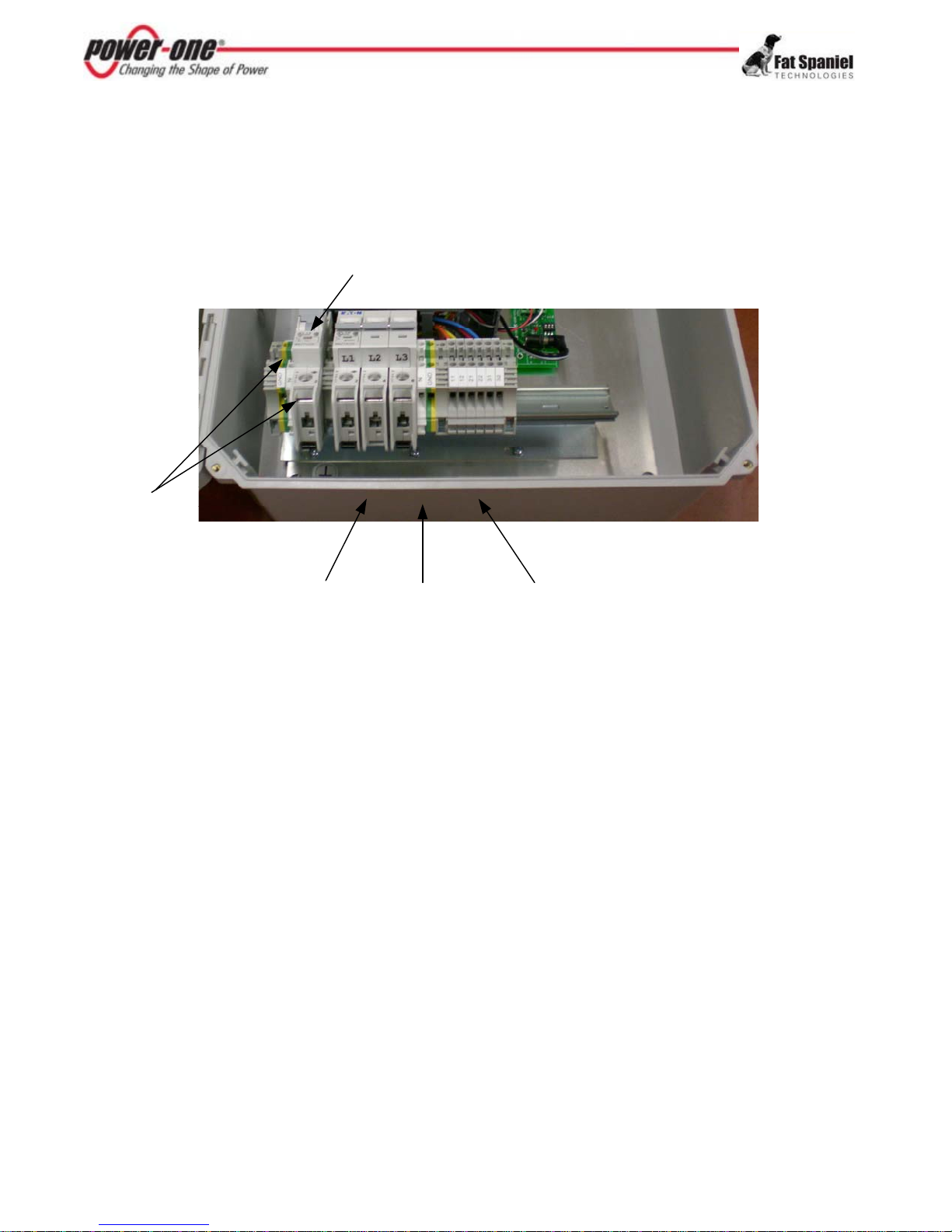
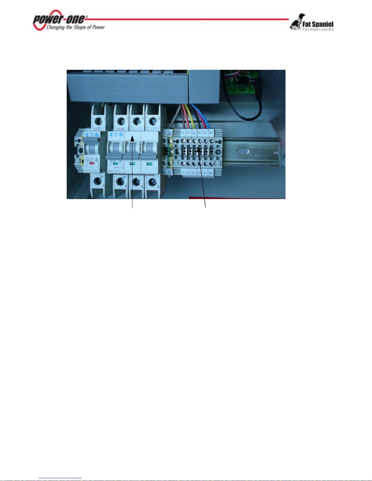
PowerSupply/MeterAssembly(Meteroptional)
DINRailConnectorBlock
Accountname/Passwordforaccesstoinverterdata
Power‐OneAuroraInverter(s)
MountingHardware,includingcabletiesandconduit
120Vwalloutletor120/230/208/240Vaccircuitpower
RS45Signalcablefrominvertertodatalogger
Straight‐throughCAT‐5NetworkcabletoLANportor
aCellularRouter
SiteSelectionandMounting
SiteLocationPlanning
Site selection depends on how many inverters you are connecting to the Aurora Universal and if
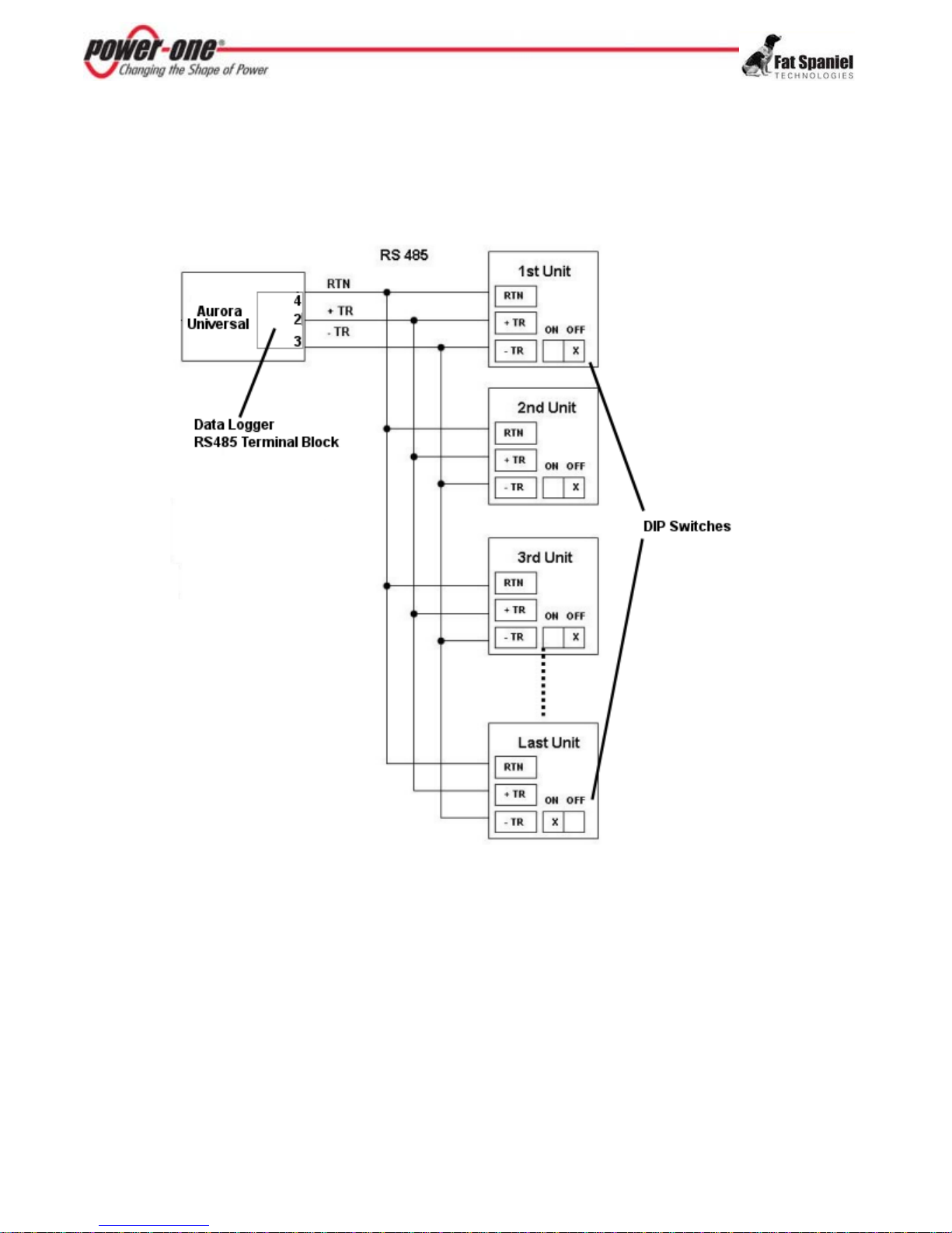
other devices are being connected to the system. For multiple inverters, inverters are “daisy-chained”
together using twisted pair signal cable with the first inverter in the chain connected to the Aurora
Universal. The Aurora Universal is connected to the internet using CAT-5 or CAT-5 compatible
cabling.
For sites with multiple inverters or long distances between interconnections, if may be useful to draw
a map of site installation, so you are sure the selected site is appropriate.
The internet connection is only limited by the typical restraints and conditions that apply to any data
network, as long as the router connected to the Data Logger is reachable over a public network. The
internet connection point may be a router or switch that is connected to a public network. It may also
be a cellular router affixed within the Aurora Universal enclosure or a cellular router shared by
multiple Aurora Universal systems.
If connecting other inverters/device types to the Aurora Universal System such as an environmental
measurement system, these devices must be connected through the secondary DB9 adapter card.
CablingRequirements
Below are the rules regarding cable lengths:
• Maximum 100 m (300 ft) between Aurora Universal and the internet connection point (LAN)
• Maximum 1,000 m (3,000 ft) between Aurora Universal and the last inverter
• Maximum 1,000 m (3,000 ft) between Aurora Inverters
• Maximum 1200 m (4,000 ft) overall length of daisy-chained inverters
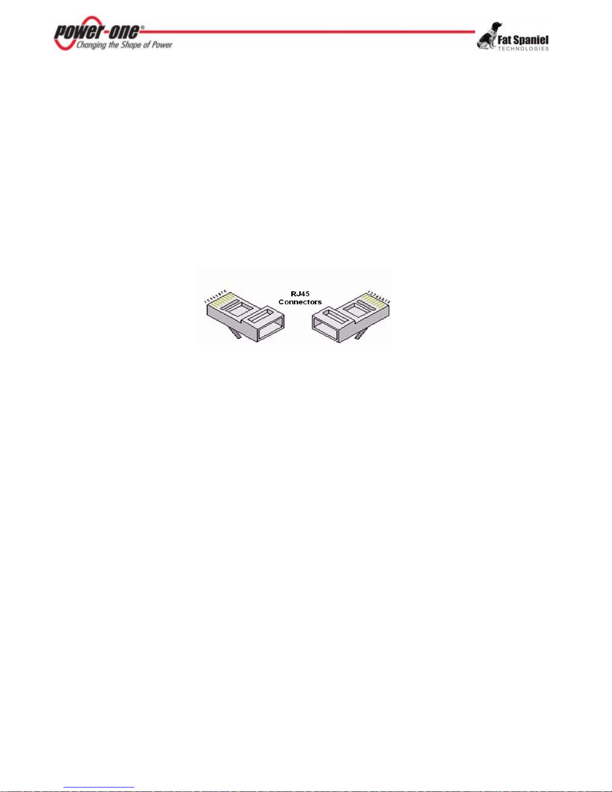
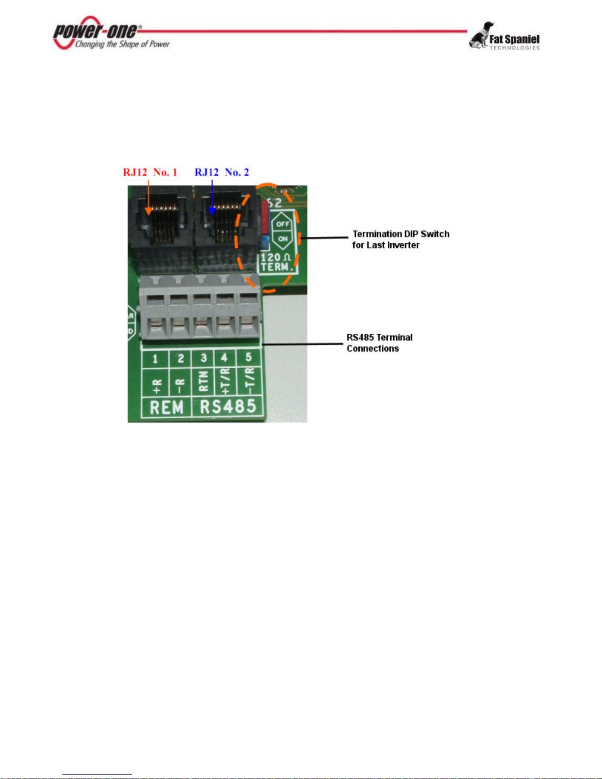
RS45 signal wiring between inverters is low-voltage wiring and should be shielded from electrical
interference, such as high voltage wires or fluorescent light ballasts.
3