Potter PSN-1000 User manual

Potter Electric Signal Company, LLC
St. Louis, MO
Customer Service: (866) 240-1870 • Technical Support: (866) 956-1211 • Fax: (314) 595-6999
www.pottersignal.com
PSN-1000 & PSN 1000(E)
Installation Manual
Document 5403599-Rev. C.-04/17

PSN-1000 POWER EXPANDER-5403599-REV C-04/17
2
1. Installation Wiring Document
Type of Circuit Voltage Type Power Type
AC Connection High Voltage Non-Power Limited
Battery Connection Low Voltage Non-Power Limited
Trouble Relay Low Voltage Non-Power Limited
Low AC Relay Low Voltage Non-Power Limited
Notication Device Circuits (NACs) Low Voltage Power Limited
Input Circuits Low Voltage Power Limited
Plink RS-485 Connections Low Voltage Power Limited
P-LINK FROM
CONTROL PANEL
P-LINK REPEATER
E.O.L.
E.O.L.
GROUND
WHITE
BLACK
Battery connection (non-power limited).
Use two (2) 12V batteries connected in series.
PSN-1000
POWER SUPPLY
P/N 5409083-B (12/21/2016)
120VAC 50Hz~60Hz
240VAC 50Hz~60Hz
Connect to separate
unswitched AC circuit
FUSE
120|240
Common relays are
non-power limited.
TROUBLE
NC COM NO
LOW AC
NC COM NO
BATTERY -
BATTERY +
Primary AC
120VAC 50Hz~60Hz, 5.1 AMP
Min Low AC Detect 98VAC
240VAC 50Hz~60Hz, 2 AMP
Min Low AC Detect 194VAC
Common Relays
3A @ 125VAC (Resistive)
3A @ 30VDC (Resistive)
Battery Charging
27.3VDC @ 1A
Low Battery Detect @20.4VDC
Earth Fault to Any Terminal
0 Ohms
Fuse Specification
8A-250VAC Time-Lag
- I2 +
- I1 +
- NAC2 +
- NAC1 +
- NAC4 +
- NAC3 +
- NAC6 +
- NAC5 +
- +
IN
A B
P-LINK
- +
OUT
A B
RPTR
COMM
MAIN
COMM
BULK
COMM
P-LINK
- +
A B
120/240 VAC
Jumper Position
F.C.C.
This device has been veried to comply with FCC Rules Part 15,
Class A Operation is subject to the following conditions:
1. This device may not cause radio interference.
2. This device must accept any interference received including any
that may cause undesired operation.
Requirements
CAUTION:
De-Energize Unit Prior to Servicing
System must be fully tested after installation.
Intended for indoor use in dry locations only.
Separation of power limited wiring from non-power limited wiring must be at least 1/4".
Install in accordance with installation manual Part Number 5403599 Rev __,
NFPA 70, 72, 12, 12A, 13, 15, 16, 17, 17A, 750, 2001

PSN-1000 POWER EXPANDER-5403599-REV C-04/17
3
Main Supply Circuit
The AC terminals are located on the power supply board. The power supply board supervises the main AC
power and provides indication that the AC power is absent.
Figure 1
The terminals are rated at 120 VAC/240 VAC 50/60 Hertz and are marked so accordingly on the board. The
earth ground connection is marked as “G” and is the furthest connection from the line voltage connection.
The AC input power ratings:
Maximum of 5.1A at the nominal 120 VAC rating.
Maximum of 3A at the nominal 240 VAC rating.
Rechargeable Battery Circuit
The battery charging circuit is provided on the power supply board. Terminal connections are provided to con-
nect wire leads for battery connection. The battery must be a recognized or listed sealed lead acid battery or
equivalent.
The battery charging voltage is approximately 27.3 VDC and the circuit is supervised. The battery circuit is
protected with a non-replaceable 7 amp poly switch located on the main circuit board. The maximum battery
charging circuit is 1.0 amp DC.
The battery circuit is rated for 8 to 55 AH batteries and the cabinet will house up to two 18 AH batteries. The
batteries will operate the panel for at least 24 hours and 5 minutes of alarm. In order to determine the minimum
size batteries for standby and alarm times desired, the installer must complete a battery calculation work sheet
in order to determine the minimum battery size for a particular application. For reference, the battery calcula-
tion work sheet is attached as Appendix A. Complete standby battery calculations must be completed to ensure
adequate battery sizes are provided.
BWG
AC120V /AC230V,50/60Hz
AC POWER
Black
White
Ground
120VAC 50/60 Hz
240VAC 50/60 Hz
Connect to separate
Unswitched AC circuit

PSN-1000 POWER EXPANDER-5403599-REV C-04/17
4
Figure 2
Separation of Circuits - Power Limited, Non-Power Limited, High Voltage Wiring
The main AC power connection is considered high-voltage and non-power limited. Battery conductors, and
the alarm, supervisory, and trouble relays are non-power limited. All remaining circuits are low-voltage, power
limited connections.
Proper separation must be maintained between the circuits listed above. All separations in the different wiring
must be maintained by at least 0.25 inches and the wire insulation must be for the higher voltage.
In the enclosure there are sufcient knock outs located around the periphery of the cabinet to allow the installer
to maintain separation between power limited and non-power limited connections. The main AC power connec-
tion should be made on the left side or top left of the cabinet.
Notication Appliance Circuits (NACs)
The PSN-1000 is equipped with six NAC circuits. Each of the circuits is rated for a continuous 3 amps at 24
VDC. The outputs are supervised and regulated. The NACs reverse polarity upon activation and the board and
illustrations are marked accordingly.
The NAC circuits can be congured for Class A operation. Class-A operation is accomplished by using a pair of
NAC circuits. Therefore, the PSN-1000 can provide 3 Class A circuits, each rated for a continuous 3 amps at 24
VDC. The outputs are supervised and regulated.
NAC circuits are power limited and the type of output is selectable. The NACs may be congured for strobe
synchronization with Potter/AMSECO, Wheelock, Gentex, or System Sensor strobe devices as shown compat-
ible in this document and the installation instructions.
The maximum impedance is a function of the load being applied to the circuit. In order to calculate the maxi-
mum impedance as follows
(Alarm Current of Notication Appliances) X (Wire Resistance) < 3 volts.
The NAC circuits may be congured for Class A, Style Z or Class B, Style Y.
The panel has ground fault detection on the NAC circuits. The impedance to ground for ground fault detection is
0 ohms.
BATTERY
-+
12 V
Battery
-+
12 V
Battery
-+

PSN-1000 POWER EXPANDER-5403599-REV C-04/17
5
I1 + - NAC 1 + - NAC 5 + - NA
C
5.1k EOL
Potter Part #3005013
Notification
Appliance
I2 + - NAC 2 + - NAC 4 + - NA
C
Figure 3 (Class B NAC)
The end of line resistor is a 5.1K ohm resistor. The resistor assembly has been evaluated in past projects and
is a standard in the Potter panel product line. The Potter part number for the listed end of line assembly is
3005013 EOL Resistor Assembly.

PSN-1000 POWER EXPANDER-5403599-REV C-04/17
6
Figure 4 (Class A NAC)
Class A operation requires that two NAC circuits be utilized as shown in Figure 4. Up to 3 Class A circuits can
be congured by pairing NAC 1&2, NAC 3&4 and NAC 5&6.
I1 + - NAC 1 + - NAC 5 + - NA
C
Notification
Appliance
I2 + - NAC 2 + - NAC 4 + - NA
C

PSN-1000 POWER EXPANDER-5403599-REV C-04/17
7
Input Circuits
The panel is equipped with two input circuits, I1 and I2. These circuits are dry-contact monitoring inputs, and
can be used in class B mode only. I1 and I2 are low voltage, power limited, and supervised.
Maximum wiring resistance = 100 ohms.
Maximum wiring capacitance = 1 uF.
Maximum wire length = 10,000 feet.
Maximum IDC voltage = 24 VDC
Maximum IDC current = 15 ma
The panel has ground fault detection on the input circuits. The impedance to ground for ground fault detection
is 0 ohms.
Figure 5 (Input Circuit as Class B Dry Contact Input)
The end of line resistor is a 5.1K ohm resistor. The resistor assembly has been evaluated in past projects and
is a standard in the Potter panel product line. The Potter part number for the listed end of line assembly is
3005013 EOL Resistor Assembly.
- I1 + - NAC 1 + - NAC 5 + - NA
C
- I2 + - NAC 2 + - NAC 4 + - NA
C
5.1k EOL
Potter Part #3005013
Normally Open
Dry Contact

PSN-1000 POWER EXPANDER-5403599-REV C-04/17
8
P-Link from Control Panel
The control panel communicates with the PSN-1000 via the main P-Link circuit. This connection is electrically
isolated from the rest of the PSN-1000. All supervision of the PSN-1000 is conducted through this connection.
Figure 6
P-Link Repeater
The P-Link repeater output allows for system expansion by reconditioning and repeating all P-Link communi-
cations. The PSN-1000 repeater output provides an additional 1 amp at 24 VDC which can be used to power
additional P-Link devices such as LCD Annunciators and/or SLC Loop expanders.
Wiring is fully supervised and power limited. Any connection to ground of 0 ohms will be annunciated as a
ground fault.
P-Link Current = 1 Amp Each
P-Link Voltage = 24 VDC
Maximum wire length = 6,500 feet.
Maximum wire resistance = Maximum wiring resistance is based on load.
Calculate using the following equation
(Total P-Link Alarm Current) x (Wire Resistance) < 6 volts.
Figure 7 (P-Link Class B Wiring Example)
-+ A B
P-LINK
Wiring from Control
Panel
- NAC 3 + -
+ A B
- NAC 6 + -
+ A B
P-LINK
To the next device
- + A B
Expansion
Device
- + A B
Expansion
Device

PSN-1000 POWER EXPANDER-5403599-REV C-04/17
9
Figure 8 (P-Link Class A Wiring Example)
Releasing Device Circuit
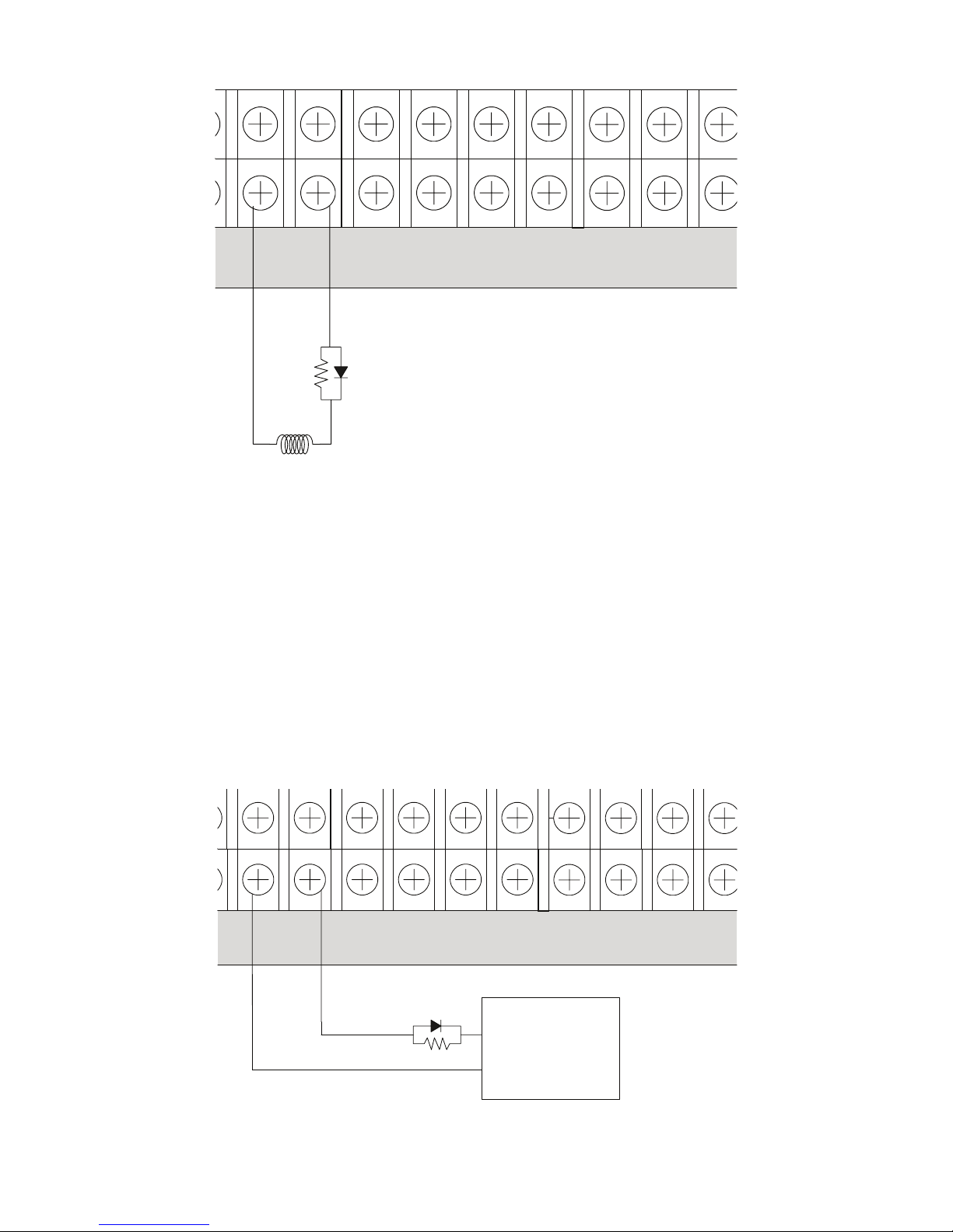
The releasing circuit is fully supervised and power limited. The releasing device circuit is a NAC that is pro-
grammed to control a releasing device such as a solenoid or squib.
The output is a constant 24 VDC, regulated output. When connected to a releasing device, the circuit is a spe-
cial application circuit and listed with the devices as outlined in Section 6 of this ULLD document.
The maximum current is 3 amps. The maximum line impedance is calculated using the following formula.
Rmax (ohm) = (24V-Vmin-0.95V)/I total
Vmin is the lowest voltage operation of the connected devices.
I total is the total current of the connected devices.
When a NAC is used as a releasing circuit, the End of Line Diode (EOLD) assembly must be installed. The
EOLD is Potter part number 3005012 and must be installed in accordance with the installation manual.
- NAC 3 + -+ A B
- NAC 6 + -+ A B
P-LINK
- + A B
Expansion
Device
- + A B
Expansion
Device
PSN-1000 POWER EXPANDER-5403599-REV C-04/17
10
- NAC 1 + - NAC 5 + - NAC 3 + -
+ A
- NAC 2 + - NAC 4 + - NAC 6 + -
+ A
P-LINK
Releasing
Device
End of line device
5.1k ohm 1/2W
Part #3005012
Note:
EOL Device shall be installed in the same
electrical enclosure as the releasing device.
Figure 9
Municipal Box Connection
When programmed as a municipal box connection, the circuit is power limited, is supervised for open and short
circuit conditions and provides a local energy connection.
Trip current = NAC1-NAC6 = 3 Amps
Max Voltage = 24 VDC
The panel has ground fault detection on municipal box connection circuits. The impedance to ground for ground
fault detection is 0 ohms.
Figure 10
- NAC 1 + - NAC 5 + - NAC 3 + -+ A B
- NAC 2 + - NAC 4 + - NAC 6 + -+ A B
P-LINK
Notes:
The EOL device shall be installed in the same electrical
enclosure as the Municipal Box.
Municipal
Box
+
-
End of line device
5.1k ohm 1/2W
Part #3005012
This manual suits for next models
1
Table of contents
Other Potter Power Supply manuals