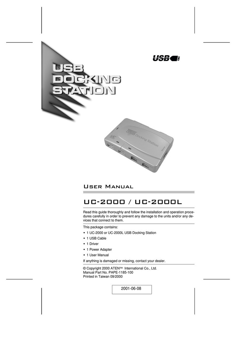
POSIFLEX DS-200 User manual

1
DS-200 DS-300
DS-210/220 DS-310/320
Package Contents
(for DS-200/300)
Dock station.................................(x1)
12V/60W power adaptor +
power cord………………………(x1)
Desktop mounting kit pack……..(x1)
(including 2 fixing screws,
2 plastic anchors, and 1 desktop
mounting bracket)
User manual…………………….(x1)
Package Contents
(for DS-210/220/310/320)
Dock station……………………(x1)
12V/100W power adaptor +
power cord……………………...(x1)
Thermal paper roll of 80 mm width
………………………………….(x1)
Spacer plate for thermal paper roll of
58mm width…………………….(x1)
Desktop mounting kit pack……..(x1)
(including 4 fixing screws, 4 plastic
anchors, and 1 desktop mounting
bracket)
User manual…………………….(x1)
DS-200/210/220/300/310/320
Dock Station
User Manual
12530901020 Ver. A0
http://www.posiflex.com

2
Views of the Dock Station
Front View
※Error LED Indicator, Paper-out LED Indicator, Printer Wi-Fi Indicator,
Feed Button, and Paper Roll Exit are provided for DS-210/220/310/320
only.
Front Inner View
※All the parts on the front inner side are provided for DS-210/220/310/320
only.
Power LED Indicator
Power Button
Paper Roll Exit
Error LED Indicator
Paper-out LED Indicator
Printer Wi-Fi Indicator
Feed Button
Paper Near End Sensor
Paper Roll Compartment
Wi-Fi Reset Button
Paper Roller

3
Rear View
DS-200/210/220 DS-300/310/320
Top View
DS-200/210/220 DS-300/310/320
Pistol Grip (PG-200/E) Holder
Bottom I/O Cover
Cable Exit
Guiding Wedge
Guiding Wedge
Tablet (MT Series) Docking Connector
Guiding Wedge

4
Bottom View
Right Side View
View of I/O Interface of DS-200/210/220/300/310/320
1
12VDC-IN Power Jack
2
RJ11 Cash Drawer Port
3
RJ45 LAN Port
4
DB-9 COM Port
5
USB 2.0 Port
Paper Roll Cover Release Lever
(For DS-210/220/310/320 Only)
1
2
3
4
5
Rubber Foot
Rubber Foot

5
Loading a Paper Roll (for DS-210/220/310/320 Only)
1. Press down the paper roll cover release lever to
release the paper roll cover.
2. The paper roll cover ejects. Then, open the paper
roll cover manually.
3. Drop the 80mm-wide thermal paper roll inside
the paper roll compartment of the printer, as
shown in the right figure.
4. Drag the paper roll to the portion where the
paper cutter is installed.
5. To avoid the printing problem occurring, push
the central portion of the paper roll cover to
close, and make the tail of the paper roll come
out of the track between the paper roll cover and
the front cover.
Press
Paper Cutter
Push

6
6. Determine that the paper roll is completely
loaded in the paper roll compartment of the
printer and the paper roll is dragged out of the
track between the paper roll cover and the front
cover.
To avoid paper jam occurring, do NOT press the printer’s
release button during printing.
When a paper jam occurs, press the release button to
release the paper cover. Then, remove the jammed paper
and reinstall the paper roll. Next, close the paper cover
properly and firmly.
If the auto cutter is also jammed, the paper cover will be
locked. Should the cutter jam be so serious to interfere the
paper cover release operation, please push the paper cover
and press the release button several times. If the problem
cannot be solved none the less, please call your local
service center for help right away.
Placing the MT Series on the Dock Station
1. Align the two dock station locking holes on the MT series tablet with the
two guiding wedges on the dock station.

7
2. Hold the portion A and press the MT series
tablet to connect firmly to the dock station.
3. Determine that the MT series tablet is completely placed on the dock
station.
Connecting Power Adapter and I/O Cables
Follow the steps listed below to open the bottom I/O cover and connect cables.
1. Press the portion A with thumb.
2. Pull the protective cover in the direction
indicated by the arrow in the right figure.
A
A

8
3. Remove the protective cover.
4. Connect power adapter and I/O cables to the
I/O port of the dock station.
5. Make the protective cover join to the wedge
portions of the rear cover of the dock
station.
6. Determine that the protective cover is well
wedged to the wedge portions of the rear
cover of the dock station. Then, gather the
I/O cables together for cable arrangement
7. Cover the I/O ports of the dock station with
the protective cover.

9
8. Determine that the I/O ports are covered and
the cable passes through the cable exit.
9. Alternatively, you can also make the cable
pass through the bottom cable exit of the
dock station, as shown in the right figure.
Mounting the Dock Station onto a Table
The dock station can be secured onto the countertop with the enclosed
mounting bracket. Please follow the steps below to mount the dock station.
1. Determine a position of a table onto which the dock station is mounted.
Then, take the desktop mounting bracket out of the desktop mounting kit
pack. Through the 2 holes formed on the bracket, drill 2 holes on the
table and plug 2 plastic anchors into the 2 holes. Then, hold the bracket
and then apply the 2 self-tapping screws into the 2 holes to secure the
bracket.
2. Align the 2 screw bolts on the bottom of the
dock station with the 2 tracks of the bracket.
Cable out
Cable out

10
3. Push hard the dock station backward along the 2 tracks of the bracket on
the table to firmly secure the dock station.
Charging the PG-200/E Battery Pack and the MT Series Tablet
After completing in placing the MT series tablet on the dock station and then
in plugging the power adaptor into the power jack on the dock station, as
described above, plug the AC power adaptor cord into an electrical outlet for
starting to charge the PG-200/E battery pack and the MT series tablet.
CAUTION!
1. When the MT series tablet operates for a period of time, the battery of
tablet will be consumed. When the tablet gives you a message
indicating it will run out of power, please place the tablet immediately
on the dock station to fully charge the battery to avoid data loss.
2. Use only the power adapter that comes with your device. Using a
different power adapter may damage your device.
At this time, the battery of MT series tablet will be immediately charged and
the battery pack loaded in the pistol grip on the DS-200/210/220 is also
charged.
When the battery pack in the pistol grip on the DS-200/210/220 is being
charged, the 4 LED indicators start to flash in green one by one from the
“LOW”level to the “FULL”level; when the battery pack is fully charged, the
4 levels of LED indicators stay solid green.
When the MT series tablet operates for a period of time, because the battery
pack loaded in the pistol grip constantly supplies power to the MT series tablet,
the battery will be consumed. When the LED indicator on the pistol grip stays
at the “LOW” level of power capacity, connect the pistol grip to the MT series
tablet and then place the pistol grip on the DS-200/210/220 for power charging,
immediately.

Other manuals for DS-200
1
This manual suits for next models
5
Table of contents
Other POSIFLEX Docking Station manuals