Pololu Corporation M2H24v14 User manual

Pololu Motoron Motor
Controller User’s Guide
1. Overview . . . . . . . . . . . . . . . . . . . . . . . . . . . . . . . . . . . . . . . . . . . . . . 2
1.1. Available versions . . . . . . . . . . . . . . . . . . . . . . . . . . . . . . . . . . . . . . 4
2. Contacting Pololu . . . . . . . . . . . . . . . . . . . . . . . . . . . . . . . . . . . . . . . . . 11
3. Getting started . . . . . . . . . . . . . . . . . . . . . . . . . . . . . . . . . . . . . . . . . . 12
3.1. Choosing the power supply and motor . . . . . . . . . . . . . . . . . . . . . . . . . . 12
3.2. Connecting everything . . . . . . . . . . . . . . . . . . . . . . . . . . . . . . . . . . . 13
3.3. Enabling I²C on the Raspberry Pi . . . . . . . . . . . . . . . . . . . . . . . . . . . . . 16
3.4. Setting I²C addresses with a Raspberry Pi . . . . . . . . . . . . . . . . . . . . . . . . 17
3.5. Setting I²C addresses with an Arduino . . . . . . . . . . . . . . . . . . . . . . . . . . 18
3.6. Writing code . . . . . . . . . . . . . . . . . . . . . . . . . . . . . . . . . . . . . . . . 20
4. Motoron M3S256 pinout . . . . . . . . . . . . . . . . . . . . . . . . . . . . . . . . . . . . . 24
5. Motoron M3 256 pinout . . . . . . . . . . . . . . . . . . . . . . . . . . . . . . . . . . . . . 26
6. LED feedback . . . . . . . . . . . . . . . . . . . . . . . . . . . . . . . . . . . . . . . . . . 28
7. I²C interface . . . . . . . . . . . . . . . . . . . . . . . . . . . . . . . . . . . . . . . . . . . 30
8. Variable reference . . . . . . . . . . . . . . . . . . . . . . . . . . . . . . . . . . . . . . . . 32
9. Command reference . . . . . . . . . . . . . . . . . . . . . . . . . . . . . . . . . . . . . . . 51
10. Cyclic redundancy check (CRC) . . . . . . . . . . . . . . . . . . . . . . . . . . . . . . . . 66
11. Reset pin . . . . . . . . . . . . . . . . . . . . . . . . . . . . . . . . . . . . . . . . . . . . 67
Pololu Motoron Motor Controller User’s Guide © 2001–2022 Pololu Corporation
https://www.pololu.com/docs/0J84/all Page 1 of 67

1. Overview
The Motoron motor controllers are a family of general-purpose modules designed to control brushed
DC motors. The Motoron receives commands via I²C, so only two I/O lines are needed regardless of
how many Motorons you connect. The Motoron modules are designed to plug into either a Raspberry
Pi or an Arduino, and multiple Motoron controllers can be stacked on top of each other, allowing
independent control of many motors.
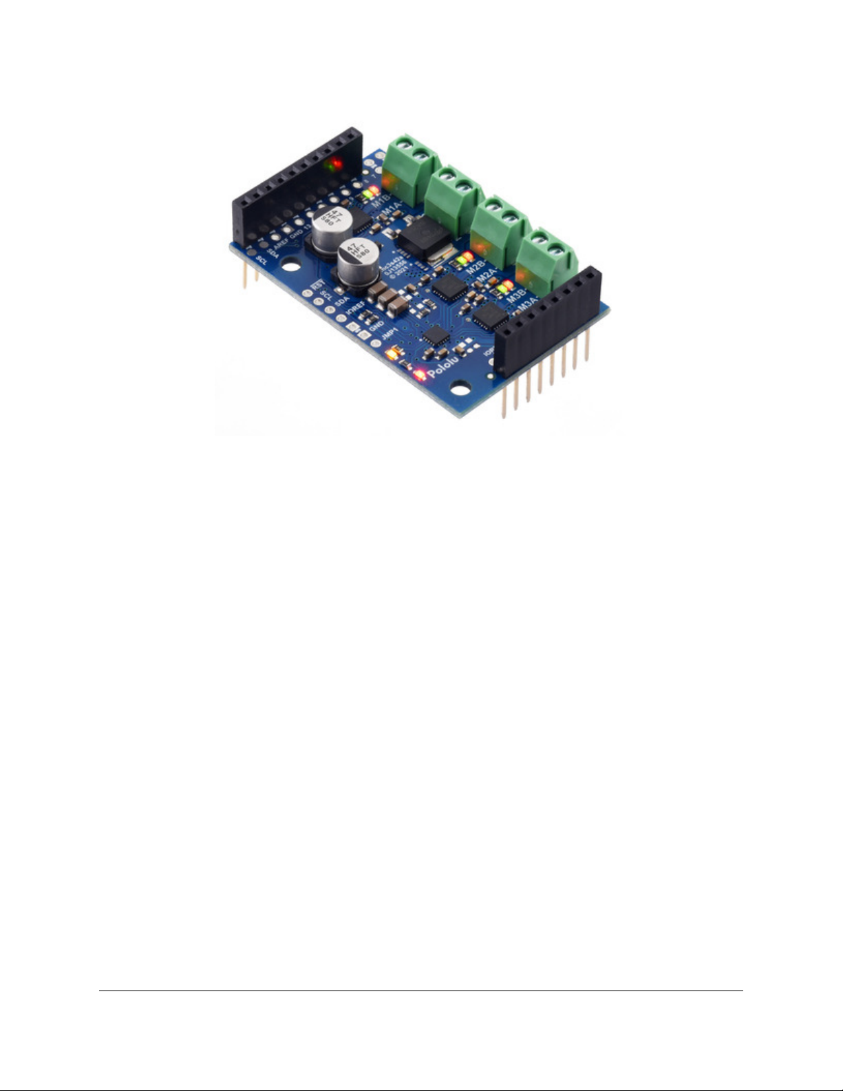
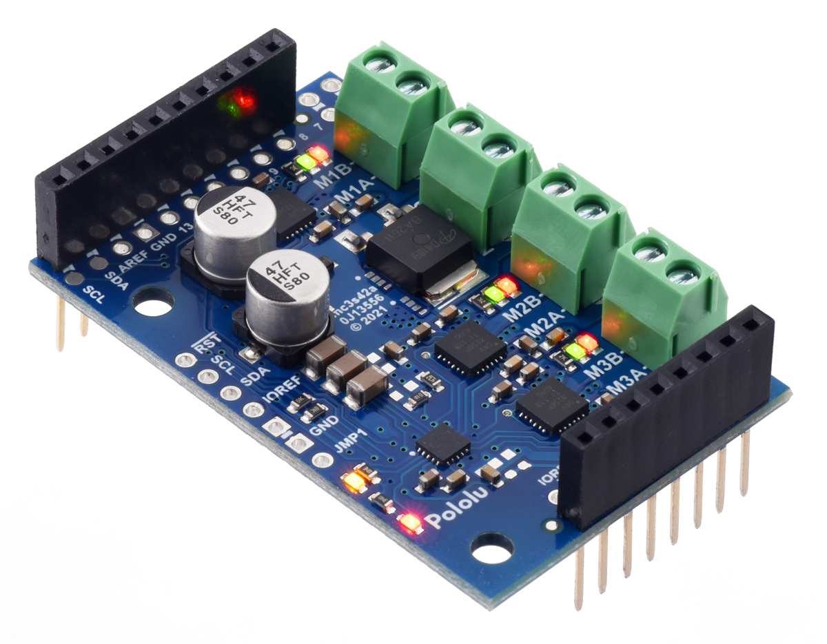
Motoron M3S256 Triple Motor Controller Shield
for Arduino (Connectors Soldered).
The Motoron M3S256 Triple Motor Controller Shield for Arduino, shown above, can control three
motors and is designed to plug into an Arduino [https://www.pololu.com/product/2191] or compatible
board, such as the A-Star 32U4 Prime [https://www.pololu.com/category/165/a-star-32u4-prime]. The
Motoron M3S256 can operate from 4.5 V to 48 V and has reverse-voltage protection on motor power
supply (down to −40 V). Its maximum continuous output current per motor is 2.0 A and it can provide
a peak current of 6.4 A for less than 1 second.
Pololu Motoron Motor Controller User’s Guide © 2001–2022 Pololu Corporation
1. Overview Page 2 of 67
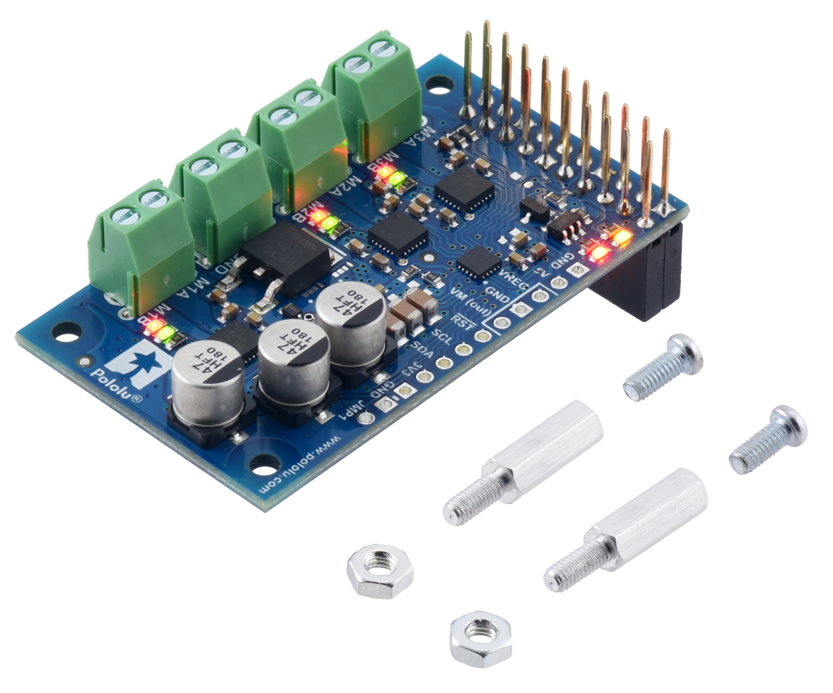
Motoron M3H256 Triple Motor Controller for
Raspberry Pi (Connectors Soldered).
The Motoron M3H256 Triple Motor Controller for Raspberry Pi, shown above, can control three
motors and is designed to plug into a Raspberry Pi. The Motoron M3 256 can operate from 4.5 V
to 48 V and has reverse-voltage protection on motor power supply (down to −40 V). Its maximum
continuous output current per motor is 2.0 A and it can provide a peak current of 6.4 A for less than
1 second.
Features and specifications
• Logic voltage range: 2.8 V to 5.5 V
• Control interface: I²C
• I²C clock speed: up to 400 k z
• Optional cyclic redundancy checking (CRC)
• Configurable motion parameters:
◦ Max acceleration/deceleration forward/reverse
◦ Starting speed forward/reverse
◦ Direction change delay forward/reverse
• PWM frequency: eight options available from 1 k z to 80 k z
• Command timeout feature stops motors if the Arduino stops functioning
• Configurable automatic error response
• Motor power supply (VIN) voltage measurement
• Optional pins make it easy to power the Arduino or Raspberry Pi from reverse-protected
Pololu Motoron Motor Controller User’s Guide © 2001–2022 Pololu Corporation
1. Overview Page 3 of 67
motor power, either directly or through an external regulator [https://www.pololu.com/category/
136/voltage-regulators] (not included)
• Two status LEDs
• Motor direction indicator LEDs
•Motoron Arduino library [https://github.com/pololu/motoron-arduino] simplifies getting started
with an Arduino or compatible controller
•Motoron Python library [https://github.com/pololu/motoron-rpi] simplifies getting started with a
Raspberry Pi
1.1. Available versions
The Motoron family consists of two different controllers: the Motoron M3S256 (an shield for Arduino)
and the Motoron M3H256 (for the Rasbperry Pi).
Multiple versions of each controller are available to provide different options for the through-hole
connectors:
•Motoron M3S256 with soldered stackable headers and terminal blocks
[https://www.pololu.com/product/5030]
•Motoron M3S256 with headers and terminal blocks included but not soldered in
[https://www.pololu.com/product/5031]
•Motoron M3S256 without any headers or terminal blocks included [https://www.pololu.com/
product/5032]
•Motoron M3H256 with soldered stackable headers, soldered terminal blocks, and
standoffs [https://www.pololu.com/product/5033]
•Motoron M3H256 with headers, terminal blocks, and standoffs included but not
soldered in [https://www.pololu.com/product/5034]
•Motoron M3H256 without any standoffs, headers, or terminal blocks included
[https://www.pololu.com/product/5035]
See below for more information about these three options.
M3S256 with connectors soldered
Pololu Motoron Motor Controller User’s Guide © 2001–2022 Pololu Corporation
1. Overview Page 4 of 67
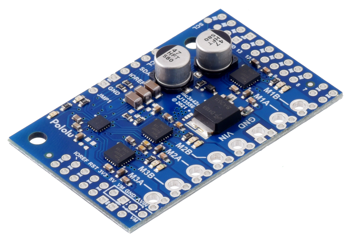
Motoron M3S256 Triple Motor Controller Shield for Arduino
(Connectors Soldered).
The M3S256 version with connectors soldered [https://www.pololu.com/product/5030] has stackable
female headers and terminal blocks installed. This version allows you to use all the main features of
the board without additional soldering, as the motor and power leads can be connected to the board
via terminal blocks and the logic connections are made by simply plugging the shield into an Arduino.
M3S256 kit version
Pololu Motoron Motor Controller User’s Guide © 2001–2022 Pololu Corporation
1. Overview Page 5 of 67

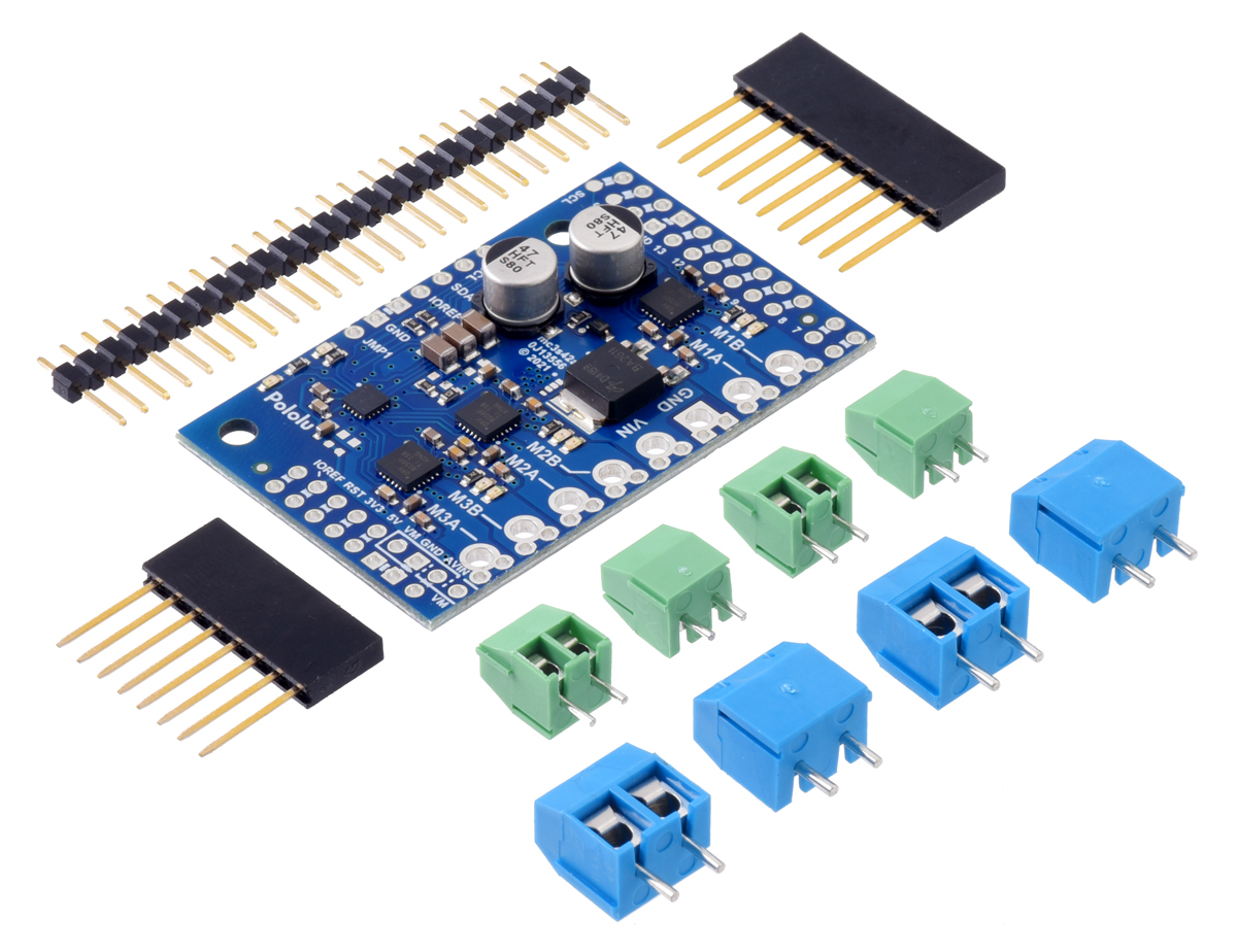
Motoron M3S256 Triple Motor Controller Shield Kit for Arduino.
The M3S256 kit version [https://www.pololu.com/product/5031] comes with the following connectors
included but not soldered, allowing for more installation options:
• One 1×10 stackable female header
• One 1×8 stackable female header
• Four 2-pin 3.5mm terminal blocks [https://www.pololu.com/product/2444]
• Four 2-pin 5mm screw terminal blocks [https://www.pololu.com/product/2440]
• One 1×25 male header [https://www.pololu.com/product/965]
There are more parts included than can be soldered to the board, providing different assembly options
to suit a variety of applications. Additional connector [https://www.pololu.com/category/19/connectors]
options are available separately, and wires can also be soldered directly to the board for more compact
installations.
Pololu Motoron Motor Controller User’s Guide © 2001–2022 Pololu Corporation
1. Overview Page 6 of 67

Note: For applications where the Motoron M3S256 will be used as a standalone board or at
the top of a shield stack, it can be assembled with the included 0.1″ male header pins and
larger (5.0mm-pitch) blue terminal blocks. For applications where the Motoron will be one
of the intermediate members of a stack of shields, we recommend assembling it with the
stackable headers and smaller (3.5mm-pitch) green terminal blocks (just like our version
with connectors already soldered [https://www.pololu.com/product/5030]). The terminal blocks
are intended to be soldered to the larger through-holes for the power and motor connections,
and the blue ones should get locked together prior to installation (see our short video on
terminal block installation [https://www.youtube.com/watch?v=6pDyTLRZ2Eg]).
M3S256 with no connectors
Motoron M3S256 Triple Motor Controller Shield for Arduino (No
Connectors).
The "no connectors" version [https://www.pololu.com/product/5032] is just the PCB assembled with all of
the surface-mount components. This version is intended for those who want to solder wires directly to
the board or use a custom set of connectors [https://www.pololu.com/category/19/connectors].
M3H256 with connectors soldered
Pololu Motoron Motor Controller User’s Guide © 2001–2022 Pololu Corporation
1. Overview Page 7 of 67

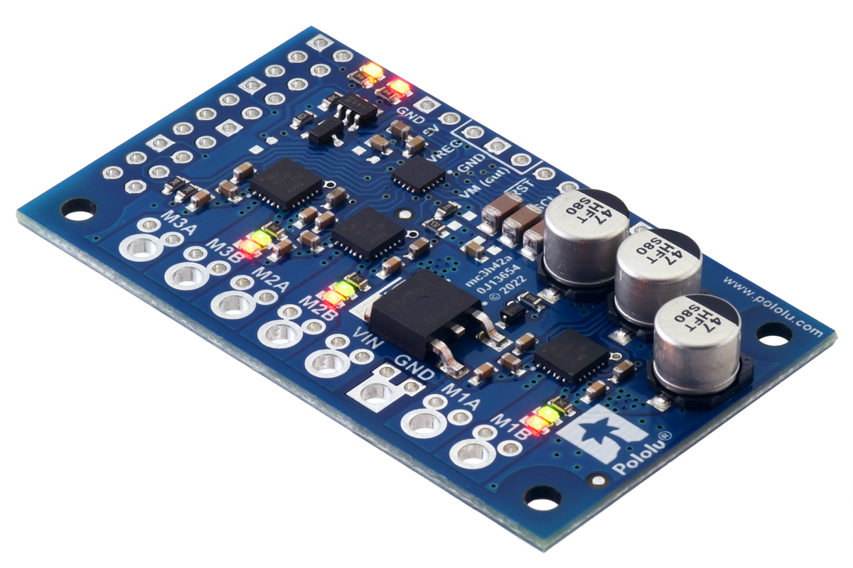
Motoron M3H256 Triple Motor Controller for Raspberry Pi
(Connectors Soldered).
The M3H256 version with connectors soldered [https://www.pololu.com/product/5033] has stackable
female headers and terminal blocks installed, and it comes with two standoffs [https://www.pololu.com/
product/1952], two screws [https://www.pololu.com/product/1968], and two hex nuts [https://www.pololu.com/
product/1967]. This version allows you to use all the main features of the board without additional
soldering, as the motor and power leads can be connected to the board via terminal blocks and the
logic connections are made by simply plugging the shield into a Raspberry Pi.
M3H256 kit version
Pololu Motoron Motor Controller User’s Guide © 2001–2022 Pololu Corporation
1. Overview Page 8 of 67

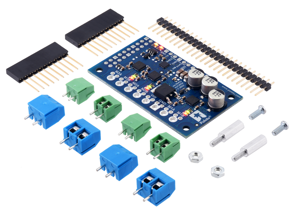
Motoron M3H256 Triple Motor Controller Kit for Raspberry Pi.
The M3H256 kit version [https://www.pololu.com/product/5034] comes with the following connectors
included but not soldered, allowing for more installation options:
• Two 1×10 stackable female headers (or one 2×10 header)
• Four 2-pin 3.5mm terminal blocks [https://www.pololu.com/product/2444]
• Four 2-pin 5mm screw terminal blocks [https://www.pololu.com/product/2440]
• One 1×25 male header [https://www.pololu.com/product/965]
• Two standoffs [https://www.pololu.com/product/1952]
• Two screws [https://www.pololu.com/product/1968]
• Two hex nuts [https://www.pololu.com/product/1967]
There are more parts included than can be soldered to the board, providing different assembly options
to suit a variety of applications. Additional connector [https://www.pololu.com/category/19/connectors]
options are available separately, and wires can also be soldered directly to the board for more compact
installations.
Pololu Motoron Motor Controller User’s Guide © 2001–2022 Pololu Corporation
1. Overview Page 9 of 67

Note: For applications where the Motoron M3 256 will be used as a standalone board or at
the top of a stack of boards, it can be assembled with the larger (5.0mm-pitch) blue terminal
blocks. For applications where the Motoron will be one of the intermediate members of a
stack of boards, we recommend assembling it with the smaller (3.5mm-pitch) green terminal
blocks (just like our version with connectors already soldered [https://www.pololu.com/
product/5033]). The terminal blocks are intended to be soldered to the larger through-holes
for the power and motor connections, and the blue ones should get locked together prior
to installation (see our short video on terminal block installation [https://www.youtube.com/
watch?v=6pDyTLRZ2Eg]).
M3H256 with no connectors
Motoron M3H256 Triple Motor Controller for Raspberry Pi (No
Connectors or Standoffs).
The "no connectors" version [https://www.pololu.com/product/5035] is just the PCB assembled with all of
the surface-mount components. This version is intended for those who want to solder wires directly to
the board or use a custom set of connectors [https://www.pololu.com/category/19/connectors].
Pololu Motoron Motor Controller User’s Guide © 2001–2022 Pololu Corporation
1. Overview Page 10 of 67
This manual suits for next models
3
Table of contents
Other Pololu Corporation Microcontroller manuals
Popular Microcontroller manuals by other brands

AMS
AMS AS7261 Demo Kit user guide

Novatek
Novatek NT6861 manual

Espressif Systems
Espressif Systems ESP8266 SDK AT Instruction Set

Nuvoton
Nuvoton ISD61S00 ChipCorder Design guide

STMicrolectronics
STMicrolectronics ST7 Assembler Linker user manual

Texas Instruments
Texas Instruments Chipcon CC2420DK user manual

Texas Instruments
Texas Instruments TMS320F2837 D Series Workshop Guide and Lab Manual

CYPRES
CYPRES CY14NVSRAMKIT-001 user guide

Texas Instruments
Texas Instruments INA-DUAL-2AMP-EVM user guide

Espressif Systems
Espressif Systems ESP8266EX Programming guide

Abov
Abov AC33M8128L user manual

Laird
Laird BL654PA user guide