Pilz PMCtendo SZ.3x User manual

PMCtendo SZ – EnDat digital
Connection plan-22199-EN-04

Contents
Connection plan PMCtendo SZ – EnDat digital
22199-EN-04 2
Section 1 Safety instructions 3
1.1 General safety instructions 3
1.2 Safety with electrical connections 3
1.3 Preventing connection errors 3
1.4 Safe functions and EMC of the drive system 4
Section 2 Connection – Motor housing to grounding conductor system 5
Section 3 EnDat 2.2 power and feedback plug connectors 6
3.1 Terminal assignment – Power plug connectors 8
3.2 Terminal assignment – EnDat 2.2 feedback plug connectors 10
Section 4 Forced ventilation unit 11
Section 5 Appendix 12
5.1 Trademarks 12
Safety instructions
Connection plan PMCtendo SZ – EnDat digital
22199-EN-04 3
1 Safety instructions
1.1 General safety instructions
WARNING!
Injury due to moving or rotating parts!
Burns due to contact with hot surfaces!
– Only connect the motor while observing the following safety instruc-
tions, the associated operating manual and any applicable national,
local or system-specific regulations.
1.2 Safety with electrical connections
DANGER!
Electric shock!
Serious injuries due to contact with live parts!
– Carry out all work on a de-energized motor!
– Make sure that the motor shaft is stationary during all work. A rotat-
ing rotor can cause high voltages at the connections.
– Disconnect the supply voltage. Be aware that there may still be dan-
gerously high voltages at the servo amplifier, even 10minutes after
switching off the supply voltage, due to the residual charge of the link
capacitors.
– Cover all open electrical connections, e.g. using protective caps.
– Secure the installation location as per regulations, e.g. using locks or
warning signs.
1.3 Preventing connection errors
CAUTION!
Damage to the motor or motor components due to electrical connection er-
rors!
– Observe the motor nameplate and this connection plan. Contact
Technical Support in case of questions.

Safety instructions
Connection plan PMCtendo SZ – EnDat digital
22199-EN-04 4
1.4 Safe functions and EMC of the drive system
CAUTION!
Damage to the motor or impairment of motor function!
Violation of EMC requirements mandated by law!
While commissioning the motor, the motor may be damaged or compliance
with legal EMC requirements may no longer be possible if you use connec-
tion cables or servo amplifiers that are not suitable for the motor. Any war-
ranty claims shall be void under these circumstances.
– Use connection cables or servo amplifiers from Pilz GmbH & Co. that
are appropriate for the motor.

Connection – Motor housing to grounding conductor system
Connection plan PMCtendo SZ – EnDat digital
22199-EN-04 5
2 Connection – Motor housing to grounding conductor
system
Connect the motor housing to the grounding conductor system of the machine in order to
prevent personal injury and faulty triggering of residual current protective devices.
All attachment parts required for the connection of the grounding conductor to the motor
housing are delivered with the motor. The grounding screw of the motor is identified with
the symbol as per IEC 60417-DB. The cross-section of the grounding conductor has to
be at least as large as the cross-section of the lines in the power connection.
EnDat 2.2 power and feedback plug connectors
Connection plan PMCtendo SZ – EnDat digital
22199-EN-04 6
3 EnDat 2.2 power and feedback plug connectors
Synchronous servo motors are equipped with twistable quick-lock plug connectors in the
standard version.
In motors with forced ventilation, avoid collisions between the motor connection cables and
the plug connector of the forced ventilation unit. In the event of a collision, turn the motor
plug connectors accordingly.
The following images show the position of the plug connectors upon delivery.
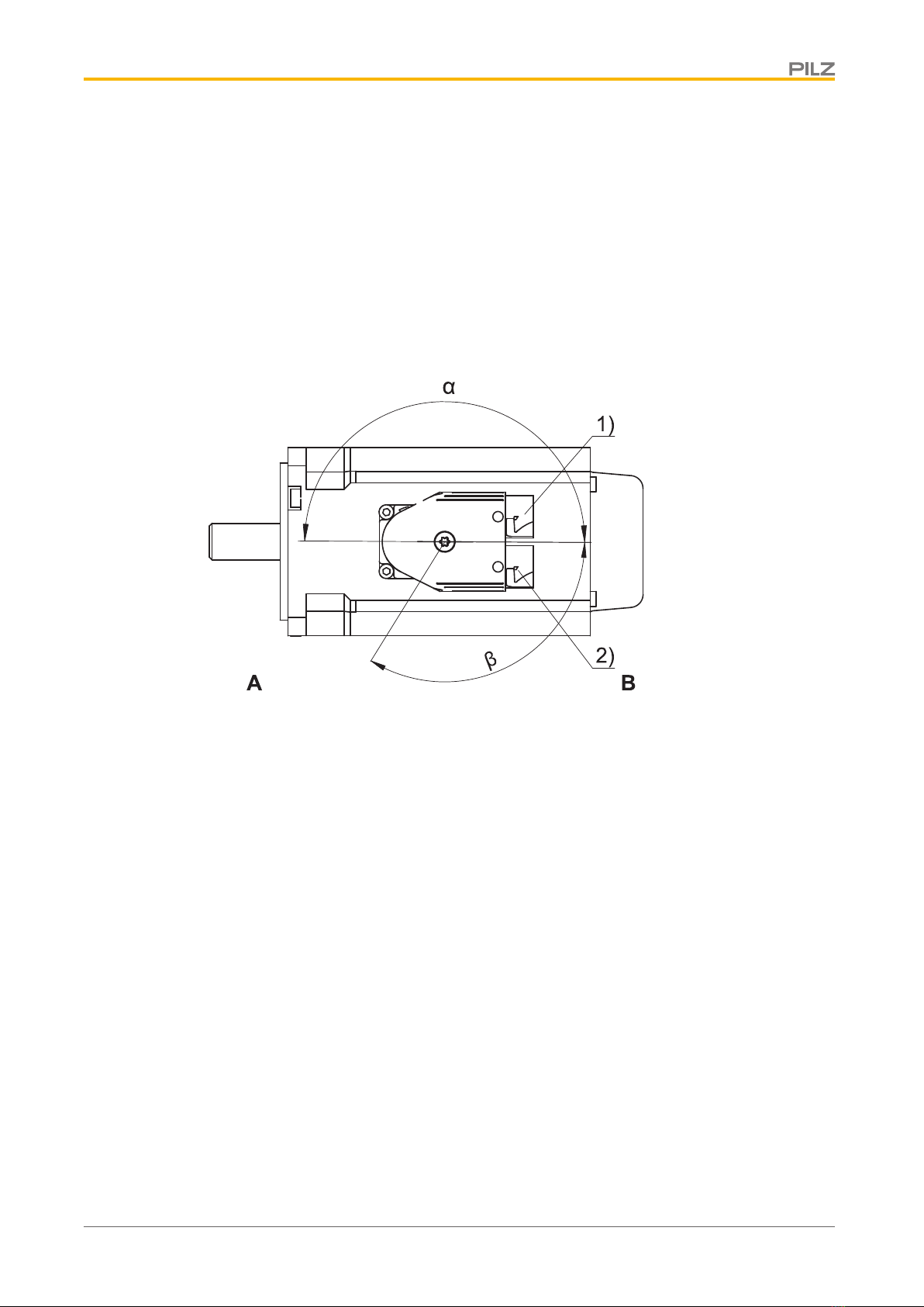
PMCtendo SZ.3x – Turning ranges of the plug connectors
Fig.: PMCtendo SZ.3x – Turning ranges of the plug connectors
Legend
1 Power plug connector 2 Feedback plug connector
A Attachment or output side of the motor B Rear side of the motor
EnDat 2.2 power and feedback plug connectors
Connection plan PMCtendo SZ – EnDat digital
22199-EN-04 7
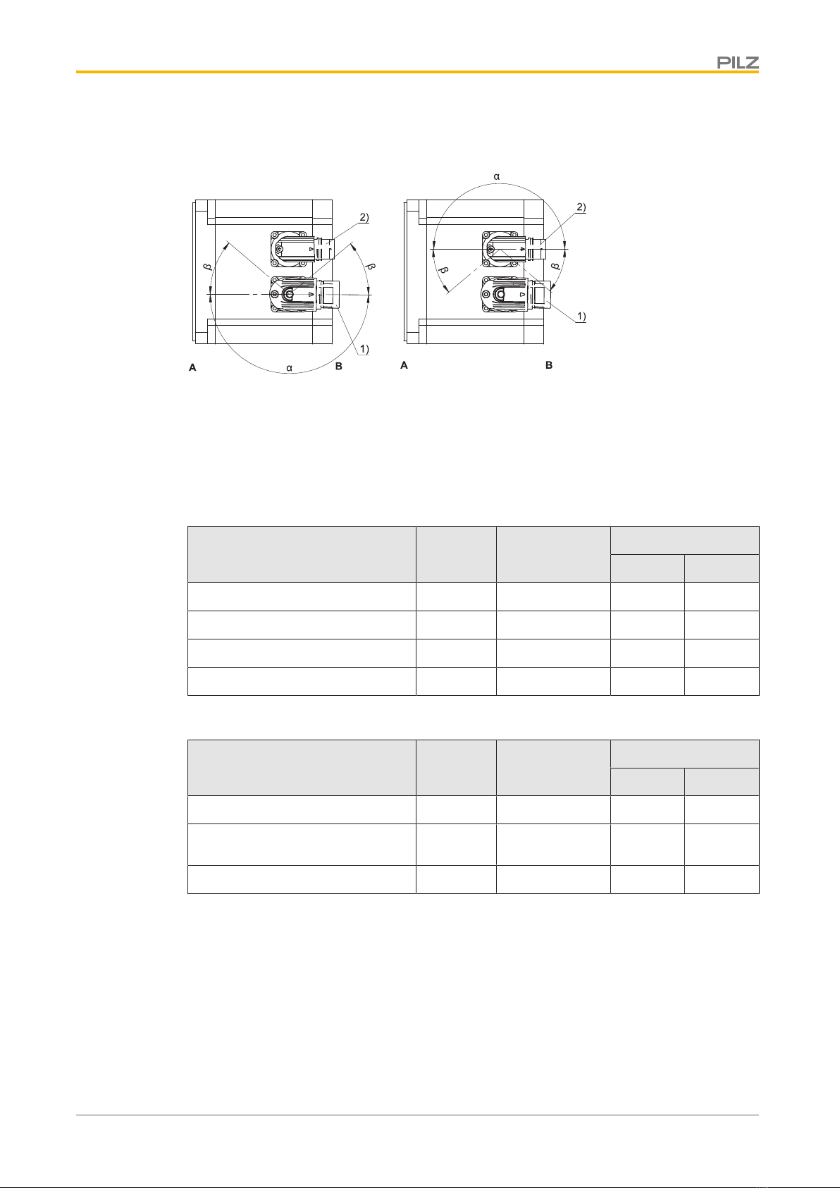
PMCtendo SZ.4x – SZ.8x – Turning ranges of the plug connectors
Fig.: PMCtendo SZ.4x – SZ.8x – Turning ranges of the plug connectors
Legend
1 Power plug connector 2 Feedback plug connector
A Attachment or output side of the motor B Rear side of the motor
Features – Power plug connectors
Type Size Connection
Turning range
α β
SZ.3x con.15 Quick lock 180° 120°
SZ.4x, SZ.5x, SZ.71, SZ.73 con.23 Quick lock 180° 40°
SZ.75, SZ.82, SZ.83, SZ.85...K con.40 Quick lock 180° 40°
SZ.85...F con.58 Screw thread 0° 0°
Features – Feedback plug connectors
Type Size Connection
Turning range
α β
SZ.3x con.15 Quick lock 180° 120°
SZ.4x, SZ.5x, SZ.7x, SZ.82,
SZ.83, SZ.85...K
con.23 Quick lock 180° 40°
SZ.85...F con.23 Quick lock 180° 0°
Notes
}The number after "con." indicates the approximate external thread diameter of the plug
connector in mm (for example, con.23 designates a plug connector with an external
thread diameter of about 23 mm).
}In turning range β, the power or feedback plug connectors can be turned only if doing
so does not cause them to collide.
}For motor type SZ.3x, the power and feedback plug connectors are connected mechan-
ically and can only be turned together.
EnDat 2.2 power and feedback plug connectors
Connection plan PMCtendo SZ – EnDat digital
22199-EN-04 8
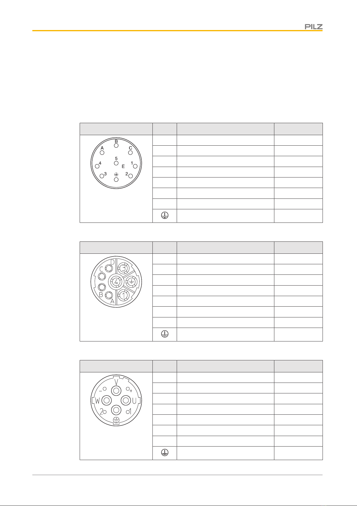
3.1 Terminal assignment – Power plug connectors
The following power plug connectors are available for PMCtendo SZ motors (the color infor-
mation relates to the connecting wires and is only relevant for the internal motor wiring).
The size of the plug connector depends on the size of the motor; terminal assignment
changes depending on the connector size.
con.15 connector size
Connection diagram Pin Connection Color
A 1U1 black
B 1V1 blue
C 1W1 red
1
2
3 1BR+ (brake + DC 24 V) red
4 1BR− (brake 0 V) black
PE green-yellow
con.23 connector size
Connection diagram Pin Connection Color
1 1U1 black
3 1W1 red
4 1V1 blue
A 1BR+ (brake + DC 24 V) red
B 1BR− (brake 0 V) black
C
D
PE green-yellow
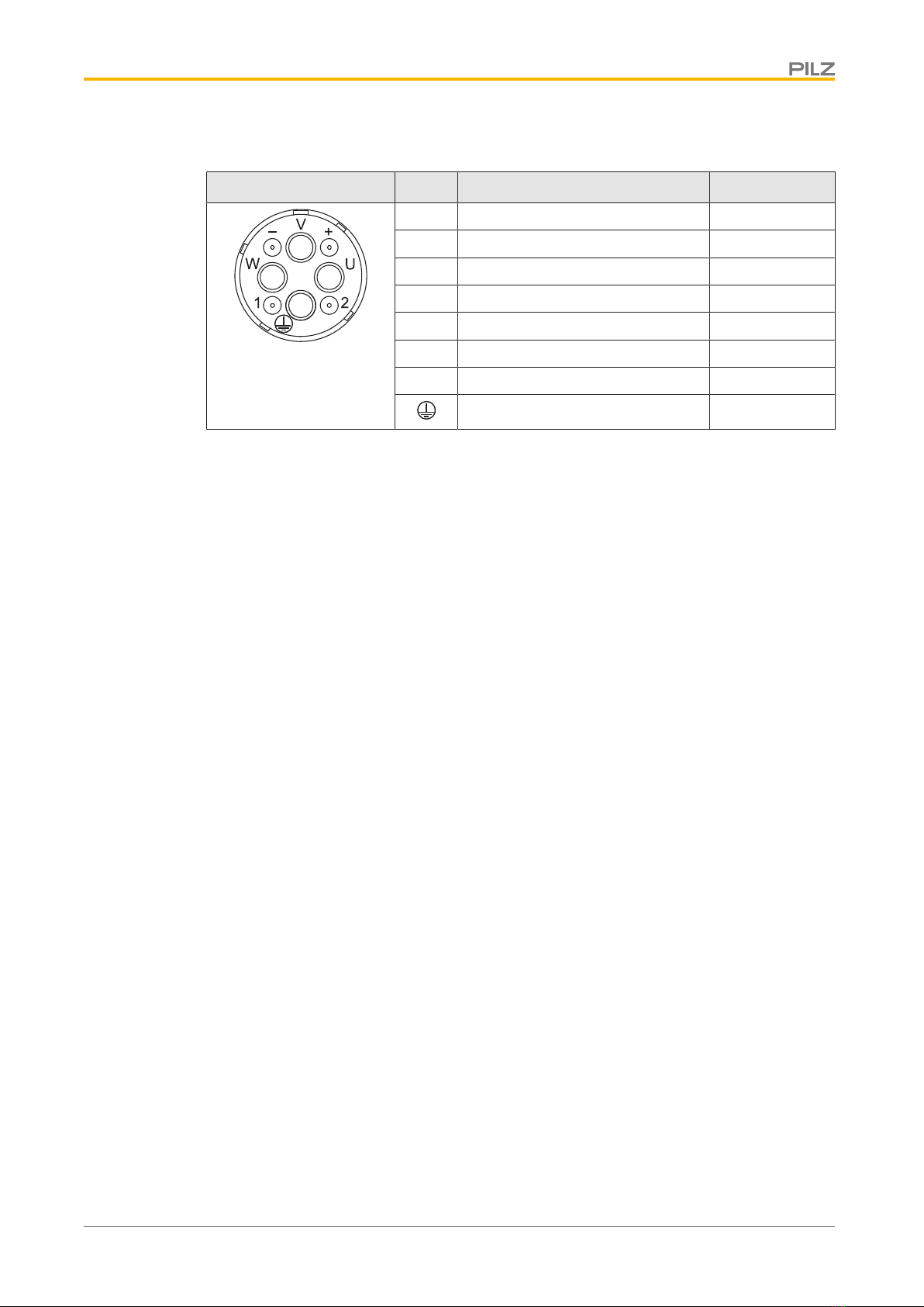
con.40 connector sizes
Connection diagram Pin Connection Color
U 1U1 black
V 1V1 blue
W 1W1 red
+ 1BR+ (brake + DC 24 V) red
− 1BR− (brake 0 V) black
1
2
PE green-yellow
EnDat 2.2 power and feedback plug connectors
Connection plan PMCtendo SZ – EnDat digital
22199-EN-04 9
con.58 connector sizes
Connection diagram Pin Connection Color
U 1U1 black
V 1V1 blue
W 1W1 red
+ 1BR+ (brake + DC 24 V) red
− 1BR− (brake 0 V) black
1
2
PE green-yellow
EnDat 2.2 power and feedback plug connectors
Connection plan PMCtendo SZ – EnDat digital
22199-EN-04 10
3.2 Terminal assignment – EnDat 2.2 feedback plug connectors
The following EnDat 2.2 plug connectors are available for PMCtendo SZ motors (the color
information relates to the connecting wires and is only relevant for internal motor wiring).
The size of the plug connector depends on the size of the motor; the terminal assignment
changes depending on the connector size.
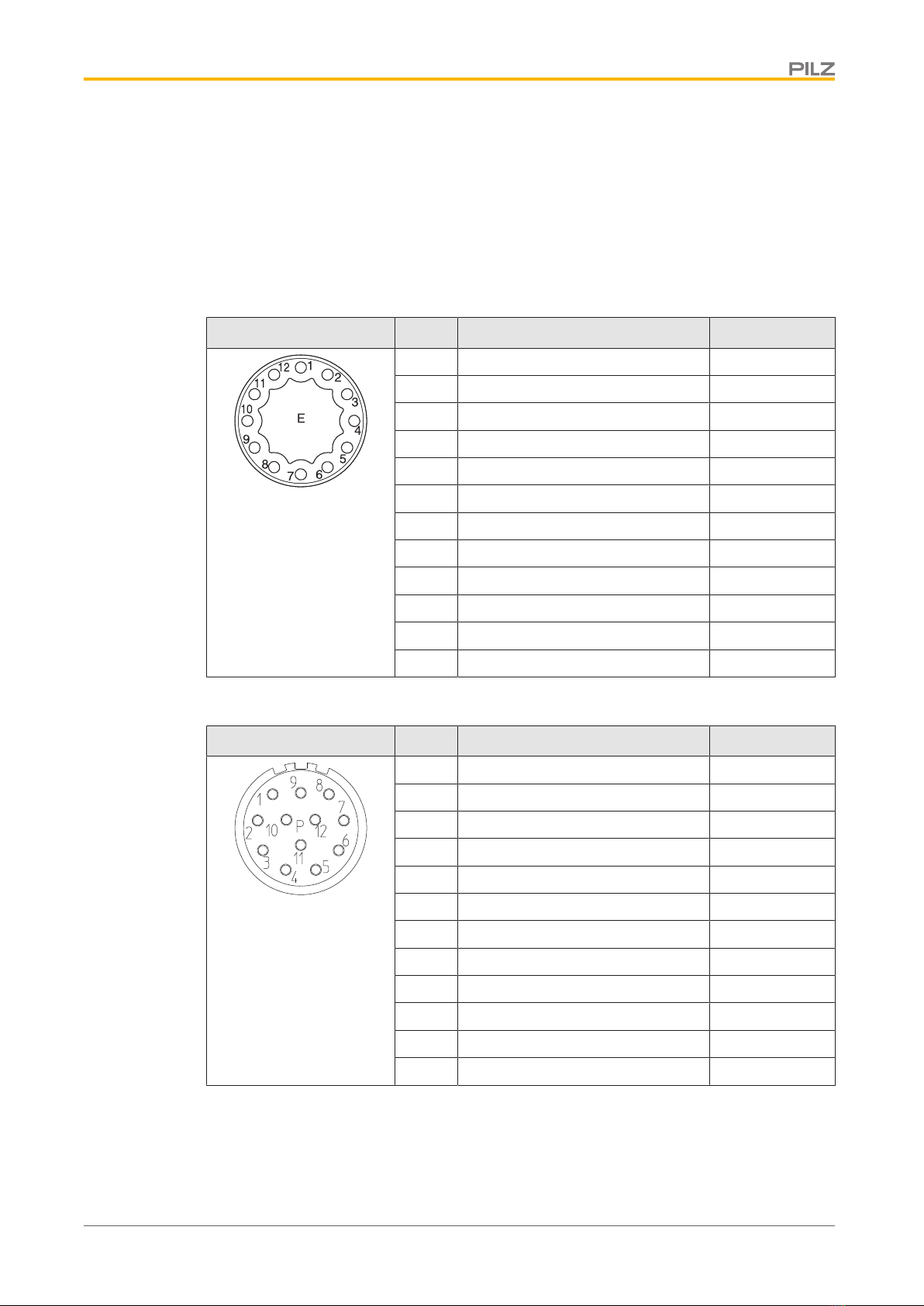
EnDat 2.2 – con.15 plug connectors
Connection diagram Pin Connection Color
1 CLOCK violet
2
3
4 PTC white
5 DATA/ pink
6 DATA grey
7
8 CLOCK/ yellow
9
10 0 V GND white green
11 PTC black
12 Up brown green
EnDat 2.2 – con.23 plug connectors
Connection diagram Pin Connection Color
1 CLOCK violet
2
3
4 PTC white
5 DATA/ pink
6 DATA grey
7
8 CLOCK/ yellow
9
10 0 V GND white green
11 PTC black
12 Up brown green
This manual suits for next models
10
Table of contents
Other Pilz Servo Drive manuals


