
PIKODER USB2PPM User manual


USB2PPM User Manual
ii
Content
Overview 3
Features 5
Pin Description and Packaging 7
Description of pins............................................................................................8
Standard application 9
LED status indication .......................................................................................9
The PiKoder Control Center PCCpro 11
Getting started..................................................................................................11
Real-time Control ............................................................................................13
PPM Settings ....................................................................................................13
Startup ...............................................................................................................13
Save Parameters ...............................................................................................14
Serial Interface 15
ASCII Command Interface............................................................................15
CompuFly USB PPM converter interface....................................................16
Joystick2PPM for Windows 19
Joystick2PPM for Android 21
System setup .....................................................................................................21
User interface ...................................................................................................22

1
Overview
The USB2PPM is a true single chip solution using a modern PIC controller
to generate an PPM-Stream with a resolution of 1 µs controlled from a Win-
dows Computer or an Android Smart device. This stream can be used by
many RC transmitters for flying with a joystick or a gamepad by simply con-
necting the USB2PPM output to the trainer connector of the RC transmitter.
This User’s Guide covers the features, the programming, and the command
interface of the USB2PPM as well as common applications.
In section 2 you will find a brief description of key features, the overall func-
tion and an overview of the interfaces supported. It is recommended to care-
fully read this section to get a good basic understanding of the USB2PPM.
The next two sections 3 and 4 deal with the controller hardware. Section 3
provides the pinning and section 4 describes the reference schematic for the
USB2PPM. Please note that the applications and interfaces described
in the following sections assume that the USB2PPM is setup in line
with this reference schematic.
Your next step is most likely to commission and test your USB2PPM. Rather
than using the “bits and bytes”-serial interfaces directly, which are laid out in
section 6, you may consider using the more sophisticated PCCpro (PiKoder
Control Center) Windows 10 software with a graphical user interface.
Section 7 demonstrates how you would interface your USB2PPM to a Win-
dows computer with a joystick or gamepad and Section 8 focusses on con-
necting the USB2PPM to an Android smart phone.
This User’s Guide is based on the most recent hard- and firmware version
2.4 available for the USB2PPM and the related PCC programming software.
Please check for updated information and new software releases on
www.pikoder.com.

USB2PPM User Manual
4
Hyperlinks were integrated into the text for convenience. You would also
find all downloads referenced on the UART2PPM webpage.
Please share with me any comments, improvement ideas or errors you will
find or encounter in working with your UART2PPM. I can be reached at
[email protected]. Thank you very much!

2
Features
This section will familiarize you with the feature set and provide a high-level
overview of the intended use of the USB2PPM allowing you to customize
the controller to your specific needs and requirements.
You can connect the USB2PPM directly to the USB port of a computer or
via USB-OTG to an Android smart device. Especially the combination of the
mobile device provides for a high degree of mobility.
The PPM stream generated by the USB2PPM is controlled via a command
protocol. More specific, the USB2PPM features a two-way ASCII-Protocol
designed to be used in combination with standard terminal programs such as
(but not limited to) Tera Term and TTY.
In addition, various application specific parameters such as startup position
after powering up, PPM polarity and number of channels can be adjusted to
your specific needs and are maintained in a non-volatile memory.
The power for the USB2PPM is usually provided through the USB port.
The key features are:
-PPM streams for 1 to 8 channels with a resolution of 1 µs
-Android app as well as Windows app for joystick or gamepad control
available
-operating voltage 5.0 V (provided by USB)
-non-volatile memory for application specific parameters
-bi-directional ASCII protocol confirming successful command exe-
cution
-support of the CompuFly USB PPM converter-protocol
-Programming application PCCpro provided for easy customization

USB2PPM User Manual
6

3
PinDescriptionandPackaging
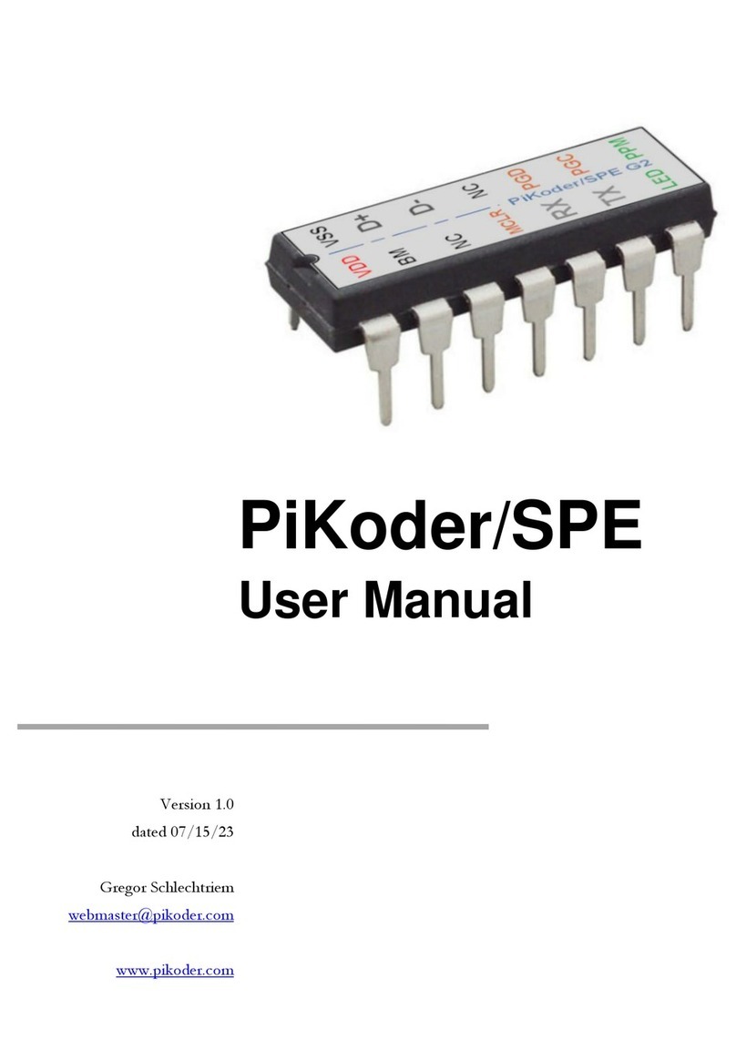
The USB2PPM comes in a 14 pin DIP package (see below). The device op-
erates from 3.3 –5 Volts. Please refer to the PIC 16F1455 data sheet from
Microchip (www.microchip.com) for complete electrical and physical speci-
fications.
A complete description of the pins is given on the following page. If a differ-
ent package would be required for your application, then please contact

USB2PPM User Manual
8
Description of pins
Pin
Symbol
Description
1
VDD
Supply voltage. Connect to 3,3 –5 V DC
2
NC
Not connected (reserved for later use)
3
NC
Not connected (reserved for later use)
4
MCLR/VPP
Reset pin, active low. Connects directly to Vss for
automatic reset at power up.
5
NC
Not connected (reserved for later use)
6
NC
Not connected (reserved for later use)
7
LED
LED indicator output (please refer to Appendix B
for more information)
8
PPM_OUT
Output pin with PPM signal
9
PGC
Clock pin for In-Circuit-Serial-Programming
10
PGD
Data pin for In-Circuit-Serial-Programming
11
VUSB3V3
Positive supply for USB transceiver; 470n capaci-
tor required
12
D-
USB data line
13
D+
USD data line
14
VSS
Ground connection

9
4
Standardapplication
The following schematic shows the standard application of the USB2PPM.
Please note that the bi-color LED indicates the USB status and is optional.
LED status indication
This following table shows the status of the USB connection (“DEVICE
STATE”) based on the LED signaling state (“LED RESPONSE”).
DEVICE STATE
LED RESPONSE
DETACHED
OFF
ATTACHED
RED
POWERED
RED
DEFAULT
RED & GREEN
ADRESS
RED & GREEN
CONFIGURED
GREEN

Table of contents
Other PIKODER Microcontroller manuals

Popular Microcontroller manuals by other brands

AMS
AMS AS7261 Demo Kit user guide

Novatek
Novatek NT6861 manual

Espressif Systems
Espressif Systems ESP8266 SDK AT Instruction Set

Nuvoton
Nuvoton ISD61S00 ChipCorder Design guide

STMicrolectronics
STMicrolectronics ST7 Assembler Linker user manual

Texas Instruments
Texas Instruments Chipcon CC2420DK user manual





Texas Instruments
Texas Instruments TMS320F2837 D Series Workshop Guide and Lab Manual

CYPRES
CYPRES CY14NVSRAMKIT-001 user guide

Texas Instruments
Texas Instruments INA-DUAL-2AMP-EVM user guide

Espressif Systems
Espressif Systems ESP8266EX Programming guide

Abov
Abov AC33M8128L user manual

Laird
Laird BL654PA user guide