
Pfaff 3371-1 series Guide

Adjustment Manual
3371-1/..
296-12-18 619/002
Justieranleitung engl. 06.05
This Adjustment manual applies to machines from software
version 0335/009
and serial number 6 001 000 onwards

The reprinting, copying or translation of PFAFF Adjustment Manuals, whether in whole or in
part, is only permitted with our previous authorization and with written reference to the
source.
PFAFF Industrie Maschinen AG
Postfach 3020
D-67653 Kaiserslautern
Königstr. 154
D-67655 Kaiserslautern

Contents
Contents .................................................................................Chapter – Page
14 Adjustment ................................................................................................................ 14 - 1
14.01 Notes on adjustment................................................................................................... 14 - 1
14.02 Tools, gauges and other accessories .......................................................................... 14 - 1
14.03 Abbreviations .............................................................................................................. 14 -1
14.04 Explanation of the symbols ......................................................................................... 14 - 1
14.05 Basic position of the machine ..................................................................................... 14 - 2
14.06 Work clamp zero point ................................................................................................ 14 - 3
14.07 Aligning the work clamp .............................................................................................. 14 - 5
14.08 Hook driver.................................................................................................................. 14 - 7
14.09 Needle height .............................................................................................................. 14 -8
14.10 Hook-to-needle clearance ............................................................................................ 14 - 9
14.11 Needle rise and needle guard ...................................................................................... 14 - 10
14.12 Aligning the hook race cover ....................................................................................... 14 - 11
14.13 Work clamp height ...................................................................................................... 14 - 12
14.14 Position of the thread wiper ........................................................................................ 14 - 13
14.15 Position of the control cam ......................................................................................... 14 - 14
14.16 Position of the control roller ........................................................................................ 14 - 15
14.17 Position of the drive shaft of the thread trimmer ........................................................ 14 - 16
14.18 Aligning the stop plate ................................................................................................ 14 - 17
14.19 Adjusting the trimmer solenoid ................................................................................... 14 - 18
14.20 Adjusting the engaging lever ....................................................................................... 14 - 19
14.21 Position of the thread catcher and knife ...................................................................... 14 - 20
14.22 Position of the release trip .......................................................................................... 14 - 21
14.23 Position of the release catch ....................................................................................... 14 - 22
14.24 Needle thread tension release .................................................................................... 14 - 23
14.25 Thread check spring and thread regulator ................................................................... 14 - 24
14.26 Bobbin winder drive wheel .......................................................................................... 14 - 25
14.27 Work clamp initiator .................................................................................................... 14 - 26
14.28 Changing the work clamp ........................................................................................... 14 - 27
14.29 Cold start ....................................................................................................................14-28
14.30 Internet update of the machine software .................................................................... 14 - 29
14.31 List of parameters ....................................................................................................... 14 - 30
14.32 Error messages on the display .................................................................................... 14 - 37
14.33 Sewing motor errors ................................................................................................... 14 - 38
14.34 OTE-errors .................................................................................................................. 14-38
15 Circuit diagrams ........................................................................................................ 15 - 1
Adjustment
14 - 1
14 Adjustment
Please observe all notes from Chapter 1 Safety
of the instruction manual! In
particular care must be taken to see that all protective devices are refitted
properly after adjustment, see Chapter 1.06 Danger warnings of the
instruction manual!
If not otherwise stated, the machine must be disconnected from the electrical
power supply.
14.01 Notes on adjustment
All following adjustments are based on a fully assembled machine and may only be carried
out by expert staff trained for this purpose.
Machine covers, which have to be removed and replaced to carry out checks and
adjustments, are not mentioned in the text.
The order of the following chapters corresponds to the most logical work sequence for
machines which have to be completely adjusted. If only specific individual work steps are
carried out, both the preceding and following chapters must be observed.
Screws, nuts indicated in brackets ( ) are fastenings for machine parts, which must be
loosened before adjustment and tightened again afterwards.
14.02 Tools, gauges and other accessories
●1 set of screwdrivers with blade widths from 2 to 10 mm
●1 set of spanners with jaw widths from 7 to 14 mm
●1 set of Allen keys from 1.5 to 6 mm
●1 metal ruler, part no. 08-880 218-00
●1 machine zero point gauge, part number 61-111 637-08
14.03 Abbreviations
t.d.c. = top dead centre
b.d.c. = bottom dead centre
14.04 Explanation of the symbols
In this adjustment manual, symbols emphasize operations to be carried out or important
information. The symbols used have the following meaning:
Note, information
Service, repair, adjustment, maintenance
(work to be carried out by qualified staff only)

Adjustment
14 - 2
14.05 Basic position of the machine
Requirement
After the machine has been switched on, it should position in t.d.c. needle bar.
●Switch on the machine.
●Hold clutch 1(screws 2) and bring the needle bar into the appropriate position by turning
the balance wheel.
●Switch off the machine.
The distance from the clutch 1to the motor plate should be 3.5 mm.
In the direction of rotation the second screw of the clutch section 3should be
on the surface of the motor shaft.
The clutch section 1should be touching the 0-ring of the axial bearing.
2
1
3,5 mm
2
3
Fig. 14 - 01

Adjustment
14 - 3
14.06 Work clamp zero point
Requirement
After the machine ahs been switched on and parameter "608" selected,
1. the needle should be centred to the hole in the adjustment gauge,
2. the switch lugs 2and 4should be centred to the respective initiator.
When removing the work clamp holder, take care that the ball bearings in the
arm support do not drop out !
●Remove the work clamp holder and the lower feed plate .
●Screw adjustment gauge 1(part no. 61-111 637-08) to the work clamp drive unit.
Preliminary adjustment
●Move the work clamp drive unit by hand in accordance with requirement 1.
●Adjust switch lug 2(screw 3) and switch lug 4(screw 5) in accordance with requirement 2.
Fig. 14 - 02
4
5
2
3
1

Adjustment
14 - 4
Fine adjustment
●Switch on the machine.
●In the input mode, select parameter "608", see Chapter 11.03 Parameter input
in the
instruction manual.
●If necessary, enter the access code, see Chapter 11.04.01 Entering the access code in
the instruction manual.
●With the corresponding plus/minus key
move the work clamp drive unit in accordance
with requirement 1, also see Chapter 11.03 Parameter input.
●Switch off the machine.
●Remove adjustment gauge 1.
●Fit the lower feed plate and work clamp holder.
If, during the fine adjustment, the setting is ± 5 increments above or below the
value in X- and Y-direction, the setting should be checked again in accordance
with requirement 2.

Adjustment
14 - 5
14.07 Aligning the work clamp
Requirement
The work clamp should be aligned in "X" and "Y" direction, so that it does not touch the
needle during sewing.
Fig. 14 - 03
2
●Switch on the machine.
●Set the sewing area size (see Chapter 9.07 Adjusting the size of sewing area
in the
instruction manual)
●In the input mode, select parameter "610", see Chapter 11.03 Parameter input in the
instruction manual
●If necessary, enter the access code, see Chapter 11.04.01 Entering the access code in
the instruction manual.
●Align work clamp 1(screw 2) so that the needle hole 3is in the centre of the work clamp
cutout.
Checking the "Y-direction"
●To check this adjustment, move along the maximum set sewing area size in "Y-direction"
by pressing the corresponding plus/minus keys
(readjust if necessary).
Y
X
1
3

Adjustment
14 - 6
TE
●Call up parameter "609".
Checking the "X-direction"
●Move along the maximum set sewing area size in "X-direction" by pressing the
corresponding plus/minus keys.
●If necessary adjust the position of work clamp 1by entering a correction value "X"
with
the corresponding plus/minus keys
in "X-direction"
in accordance with the
requirement.
●Conclude the input.
When using the max. sewing area size (X=40mm, X =20 mm), the correction
value under parameter "609" must be set at "0".
Adjustment
14 - 7
14.08 Hook driver
Requirement
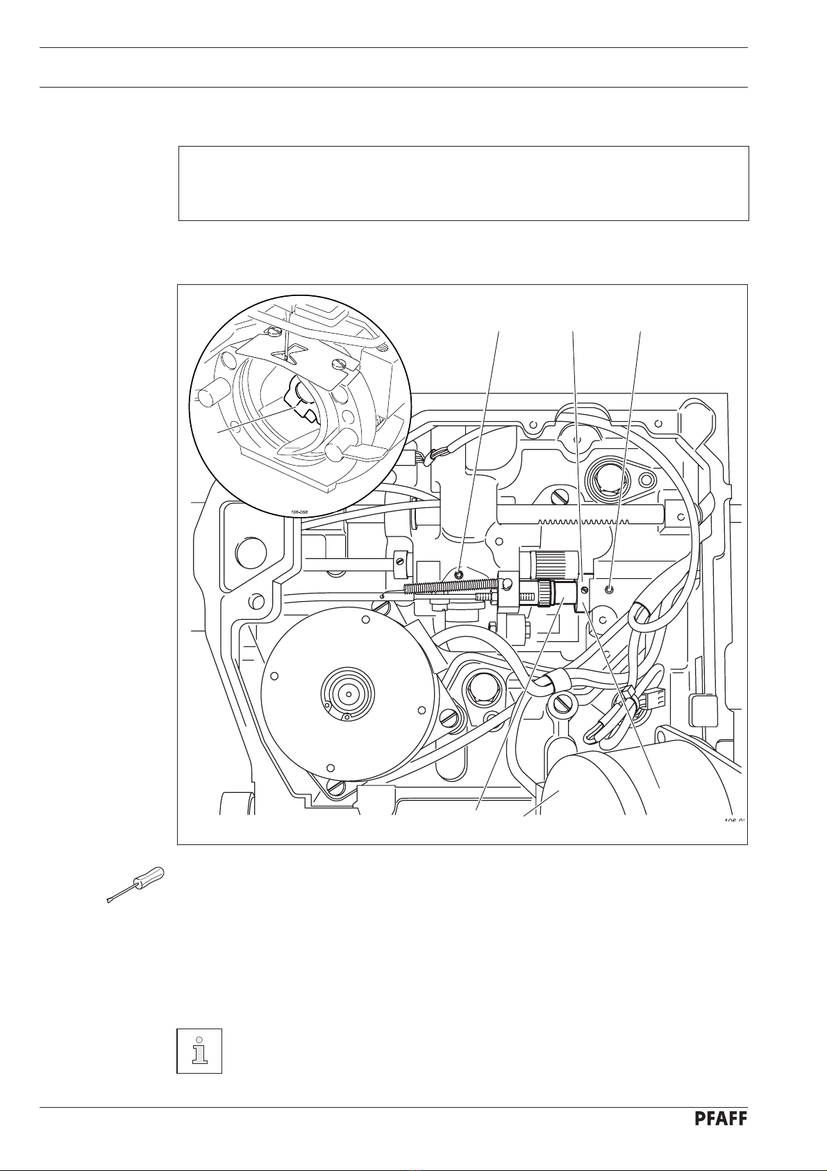
1. When the balance wheel is turned, the machine should not bind.
2. The play of catch 7should be less than 0.1 mm.
●Remove the hook.
●Loosen screws 1, 2 and 3(remove motor 4).
●Move the eccentric shaft 5in accordance with requirement 1 and twist it in accordance
with requirement 2.
●Tighten screws 1and 3.
●Move adjustment ring 6
against the metal edge and tighten screw 2.
●Insert the hook.
If catch 7has too much play, the running noise of the machine increases. Too
little play may cause the machine to jam.
Fig. 14 - 04
7
361
2
5 4
Other manuals for 3371-1 series
2
Table of contents
Other Pfaff Sewing Machine manuals

Pfaff
Pfaff hobbymatic 953 User manual

Pfaff
Pfaff creative 4.5 User manual

Pfaff
Pfaff 8301 User manual

Pfaff
Pfaff 28 User manual

Pfaff
Pfaff 487 User manual

Pfaff
Pfaff Creative 2134 User manual

Pfaff
Pfaff 131 User manual
Pfaff
Pfaff EXPRESSION 2014 User manual

Pfaff
Pfaff FreeStyle User manual

Pfaff
Pfaff 3538-20/02 Guide

Pfaff
Pfaff STITCH CREATOR User manual

Pfaff
Pfaff perfomance 2054 User manual

Pfaff
Pfaff HD SCREEN User manual

Pfaff
Pfaff 3119 User manual

Pfaff
Pfaff Series 580 Owner's manual

Pfaff
Pfaff 1244 User manual

Pfaff
Pfaff Powerline 2545 User manual

Pfaff
Pfaff 1221 User manual

Pfaff
Pfaff 3519-4/01 User manual

Pfaff
Pfaff 284 User manual


