Pfaff Industrial Seam User manual

INSTRUCTION MANUAL
Seam test station
296-12-19 210/002
Betriebsanleitung engl. 03.12

The reprinting, copying or translation of PFAFF Instruction Manuals, whether in whole or
in part, is only permitted with our previous authorization and with written reference to the
source.
PFAFF Industriesysteme
und Maschinen AG
Hans-Geiger-Str. 12 - IG Nord
D-67661 Kaiserslautern

Index
Contents ..................................................................................Page
1Proper use............................................................................................................................. 4
2Specifications ....................................................................................................................... 5
3Disposal of Machine ............................................................................................................ 6
4Explanation of symbols....................................................................................................... 7
5Controls ................................................................................................................................ 8
5.01 Summary of controls (Version without pneumatics connection) ........................................... 8
5.02 Summary of controls (Version with pneumatics connection) ................................................ 9
6Preparation ......................................................................................................................... 10
6.01 Setting the test material thickness ...................................................................................... 10
6.02 Filling the water tank ........................................................................................................... 10
7Testing..................................................................................................................................11
7.01 Testing (Version without pneumatics connection) ............................................................... 11
7.02 Testing (Version with pneumatics connection)..................................................................... 12
8Maintenance....................................................................................................................... 13
8.01 Maintenance intervals.......................................................................................................... 13
8.02 Lubrication ........................................................................................................................... 13
8.03 Manometer replacement ..................................................................................................... 13
9Parts list .............................................................................................................................. 14
4
Proper use
1 Proper use
The seam connections, which are sealed with a seam sealing tape, are checked at the seam
test station for water-tightness in accordance with DIN 20811.
The test is conducted for outdoor wear, ski, surfing and diving suits, and for shoes.
Any and all uses of this machine which have not been approved of by the
manufacturer are considered to be inappropriate! The manufacturer cannot be
held liable for any damage caused by the inappropriate use of the machine!
The appropriate use of the machine includes the observance of all operational,
adjustment, maintenance and repair measures required by the manufacturer!

5
Specifications
2 Specifications
Max. clearance underneath test plates:............................................................. approx. 38 mm
Fill water: ............................................................................................................ distilled water
Dimensions:
Length:............................................................................................................. approx. 450 mm
Width: .............................................................................................................. approx. 300 mm
Height .............................................................................................................. approx. 620 mm
Connection data:
Pressure min.:.................................................................................................................... 1 bar
Pressure max.:................................................................................................................... 6 bar
Net weight: ......................................................................................................... approx. 7,1 kg
Gross weight (mit Karton):................................................................................. approx. 11,1 kg

Disposal of Machine
6
3 Disposal of Machine
●Proper disposal of the device is the responsibility of the customer.
●The materials used for the machine are steel, aluminium, brass and various plastic
materials. The electrical equipment comprises plastic materials and copper.
●The device is to be disposed of according to the locally valid pollution control regula-
tions; if necessary, a specialist ist to be commissioned.
Care must be taken that parts soiled with lubricants are disposed of separately
according to the locally valid pollution control regulations!
Arbeitssymbole
7
4 Explanation of symbols
In this instruction manual, work to be carried out or important information is accentuated by
symbols. These symbols have the following meanings:
Note, information
Cleaning, care
Lubrication
Maintenance, repairs, adjustment, service work
(only to be carried out by technical staff)
8
Controls
0
+-
1
0. .8
0. 40.6
Fig. 5 - 01
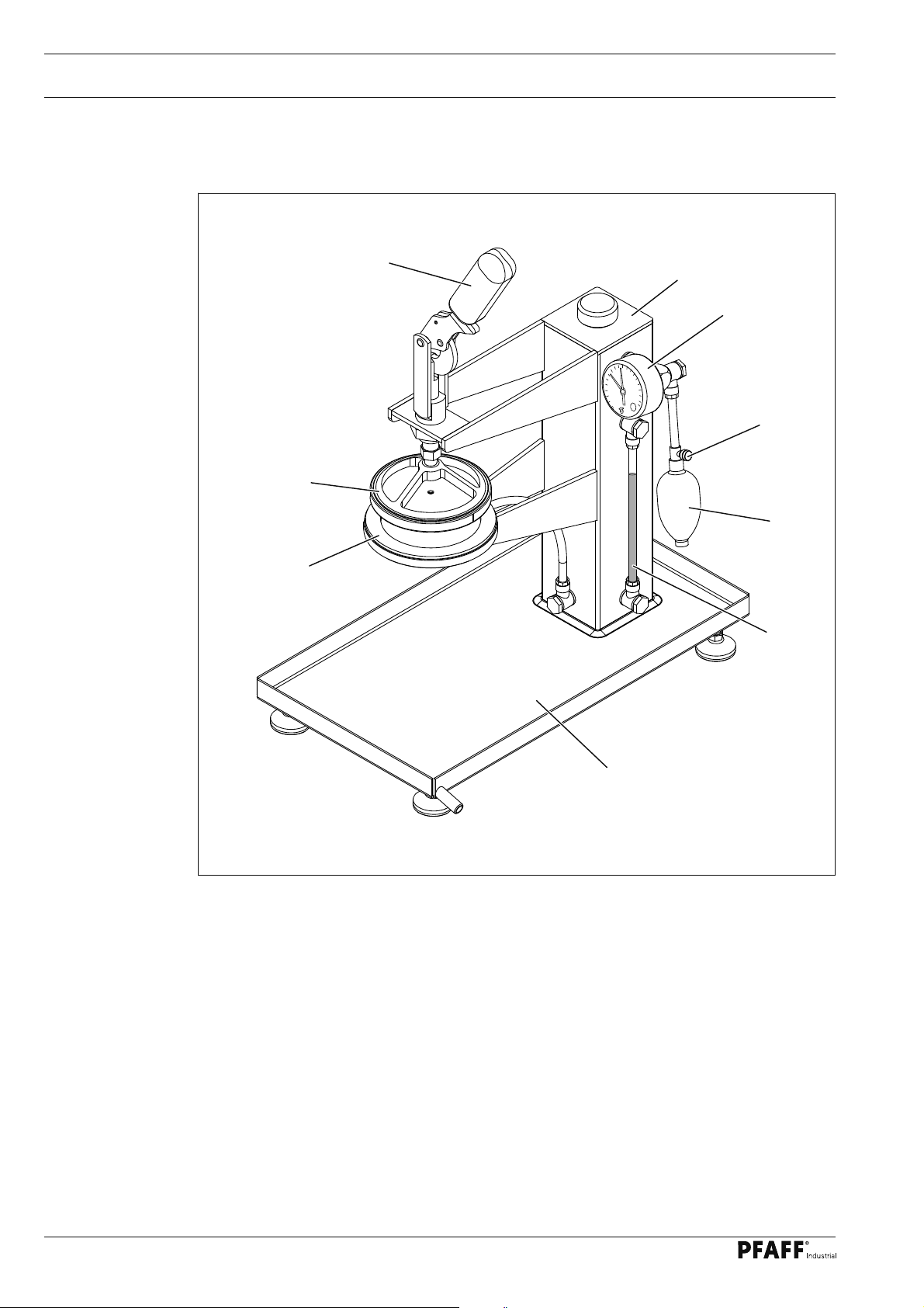
●Pressure plate 1.
●Clamping plate 2.
●Material clamping lever 3.
●Water tank 4.
●Manometer 5.
●Bleeder screw 6.
●Pump bellow 7.
●Water level display 8.
●Water collection tank 9.
5 Controls
5.01 Summary of controls (Version without pneumatics connection)
2
4
5
6
7
1
9
3
8

9
Controls
Fig. 5 - 02
0
+-
1
0. .8
0. 4 0 .6
●Pressure plate 1.
●Clamping plate 2.
●Material clamping lever 3.
●Water tank 4.
●Air stop cock 5.
●Pressure regulator 6.
●Manometer 7.
●Water level display 8.
●Water collection tank 9.
5.02 Summary of controls (Version with pneumatics connection)
2
345
6
7
1
9
8

10
Preparation
●Screw on union nut 1.
●Insert the plastic plate or the lattice
supplied depending on the material, and
screw in place with the union nut 1.
●Loosen counter nut 2 and set the
material thickness to be processes by
turning the clamping plate 3.
The material thickness should
be set in such a way that no
water can escape during the
test process while the clamping
lever 4 is engaged, but also that
the material is not marked with
pressure marks.
0
+-
1
0. .8
0. 40.6
Fig. 6 - 01
1
6 Preparation
6.01 Setting the test material thickness
2
4
●Unscrew screw 1 from water tank 2.
●Fill the tank 2 with water, while ensuring
that it cannot escape from the pressure
plate 3.
●Replace the screw 1.
Only use distilled water to
prevent lime scale build-up.
Fig. 6 - 02
1
2
3
6.02 Filling the water tank
3
Table of contents


