PEWA Robin-Amprobe KMP7030 User manual

Users Manual
KMP7030
Loop Impedance Tester


KMP7030
Loop Impedance Tester
Users Manual
June 2011, Rev.1
©2011 Amprobe Test Tools.
All rights reserved. Printed in China
English

Limited Warranty and Limitation of Liability
Your Amprobe product will be free from defects in material and workmanship for 1 year from
the date of purchase, unless local laws require otherwise. This warranty does not cover fuses,
disposable batteries or damage from accident, neglect, misuse, alteration, contamination, or
abnormal conditions of operation or handling. Resellers are not authorized to extend any other
warranty on Amprobe’s behalf. To obtain service during the warranty period, return the product
with proof of purchase to an authorized Amprobe Test Tools Service Center or to an Amprobe
dealer or distributor. See Repair Section for details. THIS WARRANTY IS YOUR ONLY REMEDY.
ALL OTHER WARRANTIES - WHETHER EXPRESS, IMPLIED OR STAUTORY - INCLUDING IMPLIED
WARRANTIES OF FITNESS FOR A PARTICULAR PURPOSE OR MERCHANTABILITY, ARE HEREBY
DISCLAIMED. MANUFACTURER SHALL NOT BE LIABLE FOR ANY SPECIAL, INDIRECT, INCIDENTAL
OR CONSEQUENTIAL DAMAGES OR LOSSES, ARISING FROM ANY CAUSE OR THEORY. Since
some states or countries do not allow the exclusion or limitation of an implied warranty or of
incidental or consequential damages, this limitation of liability may not apply to you.
Repair
All test tools returned for warranty or non-warranty repair or for calibration should be
accompanied by the following: your name, company’s name, address, telephone number, and
proof of purchase. Additionally, please include a brief description of the problem or the service
requested and include the test leads with the meter. Non-warranty repair or replacement charges
should be remitted in the form of a check, a money order, credit card with expiration date, or a
purchase order made payable to Amprobe® Test Tools.

1
1
2
7
8
3
4
6
9
5
2
3
Rotary Switch: Select
measurement function and range
Loop impedance measurement
Short-circuit current
measurement
ON / OFF Button
Display Backlight Button
6
7
8
Non Trip test on passive RCDs
Automatic measurement reading
lock (except for measurement
range LOOP-2000Ω)
TEST Button: Starts the selected test
Display
Measuring terminal
KMP7030
Loop Impedance Tester
4
5
9
10
10
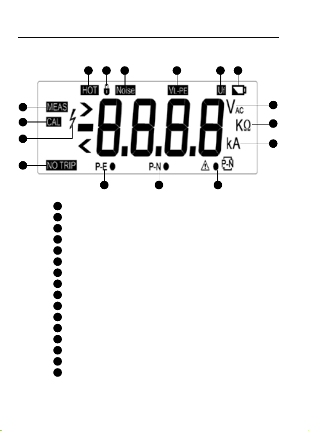
Display
1 2 3 6
7
8
4 5
9
11
10
12
13
14 15 16
1Over-temperature. Wait while the tester cools down
2Measurement reading lock
3Noise appears between neutral to earth
4Line to earth voltage
5Fault voltage. Protect earth voltage higher than 50V
6Battery status indicator
7Measuring
8Calibration mode
9Hazardous voltage
10 Non Trip test on passive RCDs
11 Voltage
12 Loop impedance
13 Prospective short-circuit current
14 Correct line and earth wire connection
15 Correct neutral and earth wire connection
16 Warning! Incorrect connection for line and neutral.
Reverse the connection.

1
KMP7030
Loop Impedance Tester
CONTENTS
SYMBOL.................................................................................................................2
SAFETY INFORMATION .........................................................................................2
UNPACKING AND INSPECTION .............................................................................3
PRODUCT DESCRIPTION........................................................................................3
FEATURES...............................................................................................................4
MAKING MEASUREMENT .....................................................................................5
Measuring Volts and Frequency.......................................................................5
Measuring Loop Impedance.............................................................................6
Measuring loop impedance NO TRIP mode ....................................................6
Measuring for Line Resistance and Prospective Short-circuit Current...........7
Fault Loop Impedance and Fault Prospective Short-Circuit Current..............8
SPECIFICATION.......................................................................................................13
MAINTENANCE AND REPAIR ................................................................................14
BATTERY REPLACEMENT.......................................................................................15

2
SYMBOLS
Caution ! Risk of electric shock Battery
Caution ! Refer to the
explanation in this Manual Earth Ground
ΩLoop Impedance Complies with EU directives
CAT III
CAT III Testers are designed to
protect against transients in
fixed equipment installations
at the distribution level.
Do not dispose of this
product as unsorted
municipal waste. Contact a
qualified recycler
Safety Information
The Tester complies with:
IEC/EN 61010-1 2nd Edition Pollution Degree 2, Measurement Category III 300V
IP40 as per EN 60529
EMC EN 61326-1
EN 61557-1, EN 61557-3
Warning: Read Before Using
• To avoid possible electric shock or personal injury, follow these
guidelines:
• Use this product only as specied in this manual or the protection
provided by the product might be impaired.
• Do not use the product if it is damaged. Before you use the product,
inspect the case. Look for cracks or missing plastic.
• Make sure the battery door is closed and latched before operating the
product.
• Remove power cord from the product before opening the battery door.
• Inspect the power cord for damaged insulation or exposed metal.
Replace damaged power cord before you use the Tester.
• Do not apply more than the rated voltage, as marked on the product.
• Never operate the product with the cover removed or the case open.
Hazardous voltage exposure is possible.
• Do not use the product if it operates abnormally. Protection may be
impaired. When in doubt, have the product serviced.

3
• Do not operate the product around explosive gas, vapor, or dust.
• Use only 1.5 V AA batteries, properly installed in the product case, to
power the product.
• Use the proper function and range for all measurements.
• Measure a known voltage and loop impedance rst to make sure that
the product operates correctly.
• Disconnect the power circuit if display shows “HOT” (overheating).
• Comply with local and national safety codes. Use personal protective
equipment (approved rubber gloves, face protection, and ame-
resistant clothes) to prevent shock and arc blast injury where hazardous
live conductors are exposed.
UNPACKING AND INSPECTION
Your shipping carton should include:
1 Loop Impedance Tester
1 UK Test Cord set
1 Strap
1 Users Manual
1 Carrying case
8 1.5V AA alkaline batteries
If any of the items are damaged or missing, return the complete package to
the place of purchase for an exchange.
PRODUCT DESCRIPTION
Loop testing is a quick, convenient, and highly specific method of evaluating
an electrical circuit for its ability to engage protective devices (circuit breakers,
fuses, RCD’s). A “loop” is defined by including unsuspected elements, where
current has found parallel paths to ground. Because a ground loop determines
the effectiveness of protective devices, it is crucial to be able to measure it, in
order to detect and correct problems.

4
FEATURES
• Non Trip Loop test on passive RCDs
• Instant reading
• 20, 200 & 2000ΩLoop measurement ranges
• PSC measurement up to 20kA
• Displays mains voltage before test
• Instant correct wiring status check
• Backlight display
• Low Battery Indication
• CAT III 300V
This product is intended to be used to measure installations in process plants,
industrial installations, and residential applications.
EN 61557-3 Measurement Range:
Function Display Range
EN 61557
Measurement Range
Operating Error
Nominal
Values
LOOP
EN 61557-3
LOOP (NO TRIP)
0.00Ω- 20.0Ω
0.0Ω- 200Ω
0.50Ω- 19.99Ω±(3% + 6LSD)
10.0Ω- 199.9Ω±(3% + 6LSD)
Un=230VAC
f = 50Hz
Ik=20kA
LOOP
(HI CURRENT)
0.00Ω- 20.0Ω
0.0Ω- 200Ω
0Ω- 2000Ω
0.50Ω- 19.99Ω±(3% + 4LSD)
10.0Ω- 199.9Ω±(3% + 4LSD)
100Ω- 1999Ω±(3% + 4LSD)
Volts 100 – 300V,
50/60Hz
100 – 300V, 50/60Hz
±(2% + 4LSD)
Ambient Temperature: 23±2°C
Ambient Humidity: 45 - 75%RH
Additional operating uncertainties from position, supply voltage temperature,
system phase angle system frequency, system voltage, harmonics and D.c
quantity. The overall operating uncertainty B% is within +/- 30%
Measurement times: approx. 8000 times or more (with new batteries)
Table of contents
Other PEWA Test Equipment manuals

PEWA
PEWA VOLTfix Series User manual

PEWA
PEWA Megger PCITS600/2 User manual

PEWA
PEWA Metrel MD 1100-LCD User manual

PEWA
PEWA AMPROBE digital User manual

PEWA
PEWA Chauvin Arnoux C.A 6423 User manual

PEWA
PEWA Amprobe LAN-1 User manual

PEWA
PEWA BEHA UNITEST TELARIS SCHLEIFE User manual

PEWA
PEWA ROBIN AMPROBE KMP 7036 User manual

PEWA
PEWA ODEN AT User manual


