
Peimar PSI-3400TLM User manual

1
PSI-3400TLM
PSI-4500TLM
PSI-5200TLM
PSI-6000TLM
MONOPHASE INVERTER
INVERTER MONOFASE
EN / IT

2

1
About this Installation Guide .......... 2
Safety Symbols............................... 3
General Safety Requirements ........ 4
Intended Use .................................. 5
Inverter Function............................. 8
Labels and Markings on
the Inverter ..................................... 9
Connections on the Inverter ......... 10
User Interface ...............................11
Unpacking..................................... 12
Mounting the Inverter.................... 14
AC- and DC-Connection............... 17
Starting the Inverter...................... 21
Commissioning............................. 22
Inverter Conguration................... 24
Parallel Connection of PV-Ports ... 25
Opening the Inverter..................... 26
SD Card / Digital Input /
Digital Output................................ 27
Technical Data.............................. 32
Table of Contents
Indice
EN
IT
Informazioni sulle presenti
istruzioni per l’installazione............. 2
Simboli di sicurezza........................ 3
Avvertenze generali di sicurezza.... 4
Uso conforme ................................. 5
Funzionamento............................... 8
Avvertenze e simboli sull’inverter ... 9
Collegamenti................................. 10
Interfaccia utente ......................... 11
Disimballaggio .............................. 12
Montaggio dell’inverter ................. 14
Collegamento AC e DC ................ 17
Avvio dell’inverter ......................... 21
Messa in funzione......................... 22
Congurazione dell’inverter.......... 24
Collegamento in parallelo degli
ingressi ......................................... 25
Come aprire l’inverter ................... 26
Scheda SD / Ingresso digitale /
Uscita digitale ............................... 27
Dati tecnici.................................... 33
1

2
This installation guide describes the
safe installation of the inverters listed
on the left.
Target group:
Qualied technicians
Terms:
Installer Qualied technician
in charge of the
installation
Supplier Company the product
was purchased from
Inverter PV-inverter described
in this installation guide
About this Installation Guide EN
Le presenti istruzioni di installazione
descrivono l’installazione sicura degli
inverter elencati a sinistra.
Gruppo di destinazione:
Tecnici qualicati
Termini:
Installatore Tecnico qualicato che
esegue l’installazione
Fornitore Azienda da cui è stato
acquistato il prodotto
Inverter Inverter fotovoltaico
PSI PEIMAR descritto
nelle presenti istruzioni
per l’uso
Informazioni sulle presenti istruzioni per l’installazione IT
1
2
Normal Fault
OKESC
PSI-3400TLM
Max. DC-Power 3400 W
Max. AC-Power 3200 W
ESC OK
PSI-4500TLM
Max. DC-Power 4500 W
Max. AC-Power 4300 W
ESC OK
PSI-5200TLM
Max. DC-Power 5200 W
Max. AC-Power 5000 W
PSI-6000TLM
Max. DC-Power 6000 W
Max. AC-Power 5750 W
ESC OK
ESC OK
3
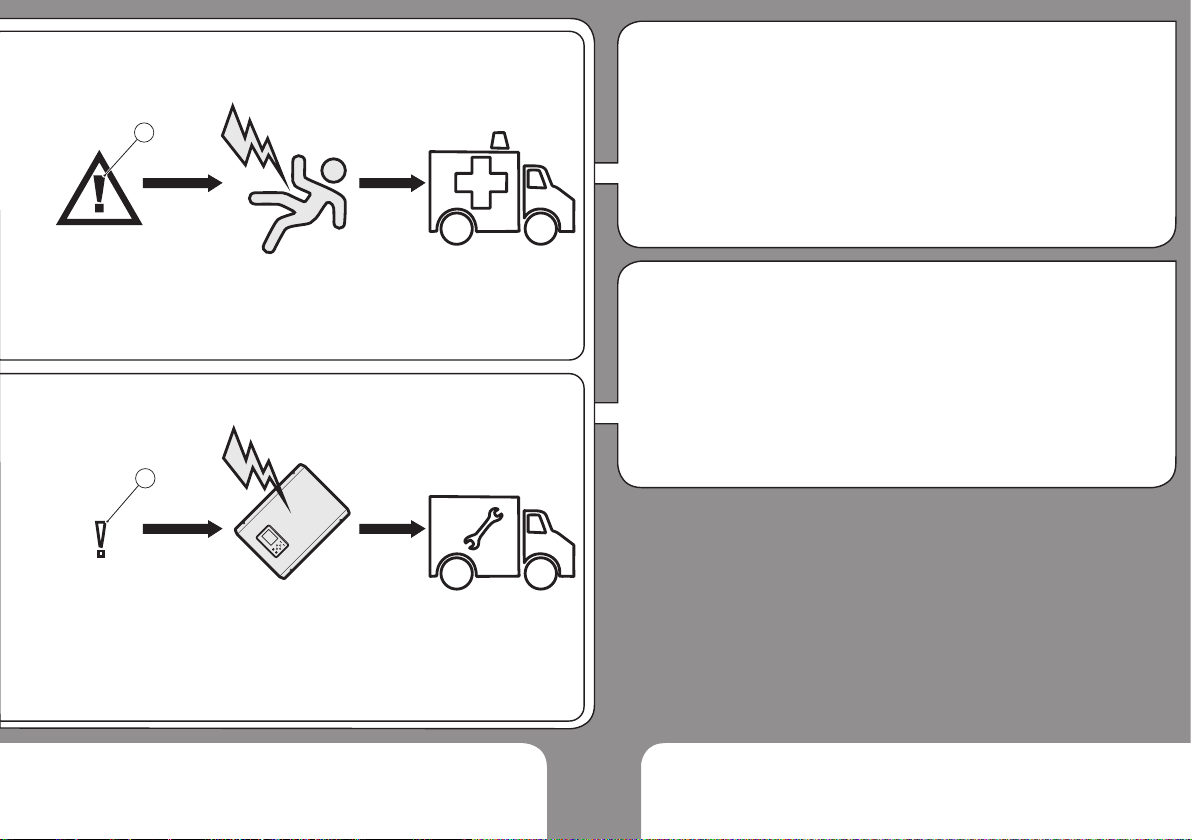
Life threatening voltages are
processed inside the inverter.
Hazardous situations that can lead to
death or serious injuries are indicated
with the “WARNING” symbol (1) on
the left.
Hazardous situations that can result in
damage of the inverter are indicated
with the “CAUTION” symbol (2) on the
left.
Countermeasures that must
be taken in order to avoid the
hazardous situation are indicated with
an arrow:
ΓThis is an example how to avoid a
hazardous situation.”
Safety Symbols
1
2
Normal Fault
OKESC
Nell’inverter vengono utilizzate
tensioni mortali.
Situazioni pericolose che possono
causare morte o lesioni gravi
sono contrassegnate dal simbolo
“AVVERTENZA” (1) a sinistra.
Situazioni pericolose che possono
causare danneggiamenti dell’inverter
sono contrassegnate dal simbolo
“CAUTELA” (2) a sinistra.
Contromisure per prevenire
la situazione pericolosa sono
indicate con una freccia:
ΓQuesto è un esempio di come
prevenire una situazione
pericolosa”.
Simboli di sicurezza
EN
IT

4
1. WARNING! Danger of electric
shock!
ÎRead Installation Guide
carefully. Follow all
instructions.
2. Contact your supplier when you
have questions.
3. Wear safety shoes when lifting
and transporting.
4. 2 people are required for
lifting and transporting.
WARNING! Danger of electric
shock and re!
ÎNever modify the inverter except
instructed otherwise by the
manufactured.
Keep this installation guide near the
inverter!
General Safety Requirements EN
?
1
ESCOK
ESCOK
4
2
3
1. AVVERTENZA! Pericolo dovuto
a scossa elettrica!
ÎLeggere attentamente le
istruzioni di installazione.
Seguire tutte le istruzioni.
2. Contattare il proprio fornitore in
caso di dubbi.
3. Indossare scarpe
antinfortunistiche se si sposta o si
trasporta il dispositivo.
4. Il sollevamento e il
trasporto del dispositivo
devono essere effettuati da 2
persone.
AVVERTENZA! Pericolo dovuto a
scossa elettrica e incendi!
ÎQualsiasi modica dell’inverter è
vietata salvo in caso di istruzioni
ricevute dal produttore.
Conservare le presenti istruzioni per
l’installazione vicino all’inverter!
Avvertenze di sicurezza fondamentali IT

5
The inverter (1) converts DC-power
from the PV-generator (2) to AC-
power. The AC-power is fed into the
grid (3). In case of a grid failure: The
inverter automatically disconnects
(4) from the grid. The inverter
automatically reconnects when the
grid is restored. The inverter can
only be used for DC-power from PV-
generators (5).
CAUTION! Risk of damaging
the inverter!
ÎDo not connect other DC-power
sources (6) such as wind power
systems, hydroelectric generators,
fuel cells or batteries.
Intended Use
L’inverter (1) trasforma la potenza
DC del generatore fotovoltaico (2)
in potenza AC. La potenza AC viene
immessa nella rete pubblica (3).
In caso di guasto di rete: L’inverter
si scollega (4) automaticamente
dalla rete. L’inverter si ricollega
automaticamente alla rete quando
essa viene ripristinata. L’inverter può
essere utilizzato solo per la potenza
DC dei generatori fotovoltaici (5).
CAUTELA! Pericolo di
danneggiamento dell’inverter!
ÎAltre fonti di potenza DC (6)
come ad es. centrali eoliche,
idroelettriche, celle a combustibile
o batterie non devono essere
collegate.
Utilizzo conforme
EN
IT

6
1. WARNING! Risk of electric
shock! The PV-panels emit a
dangerous DC-voltage when
exposed to sunlight.
2. The inverter is not
equipped with an internal
isolation transformer
3. Local regulations and standards
can require that an isolation
transformer is additionally
installed. Contact your utility
operator if you have questions.
Electrical Safety EN
DC
1
DC AC
2
AC AC
3
OK
OK
1. AVVERTENZA! Pericolo dovuto
a scossa elettrica! I moduli
fotovoltaici generano tensione DC
pericolosa quando splende il sole.
2. L’inverter non dispone di un
trasformatore di separazione.
3. Le disposizioni e le normative
in vigore possono prevedere
l’impiego di un trasformatore.
Chiedere al proprio gestore di rete.
Sicurezza elettrica IT

7
1. Local regulations and standards
can require that current-breakers
are installed on the DC-side.
Contact your utility operator if you
have questions.
2. The inverter is equipped
with an integrated RCMU
Type B (tested according to EN
62109-2 / IEC 60755). If local
regulations and standards require
an external RCD/RCM, a RCD/
RCM Type A is sufcient.
DC-Disconnect / RCD
DC -
DC+
+
-
1
L
N
PE
RCD
RCM
2
1. Le disposizioni e le normative
in vigore possono prevedere
l’impiego di sezionatori sul lato DC.
Chiedere al proprio gestore di rete.
2. L’inverter è dotato di una RCMU
integrata del tipo B (certicata
secondo EN 62109-2 / IEC 60755).
Nel caso in cui le disposizioni
e le normative locali richiedano
l’installazione di un RCD/RCM
esterno, è sufciente un RCD/RCM
de tipo A.
Dispositivo di sezionamento DC / RCD
EN
IT
8
5
DC2-
DC2+
DC1+
DC1-LN
PE
7
4
3
2
1
6
9
SD
8
RS485
WiFi
12
10
11
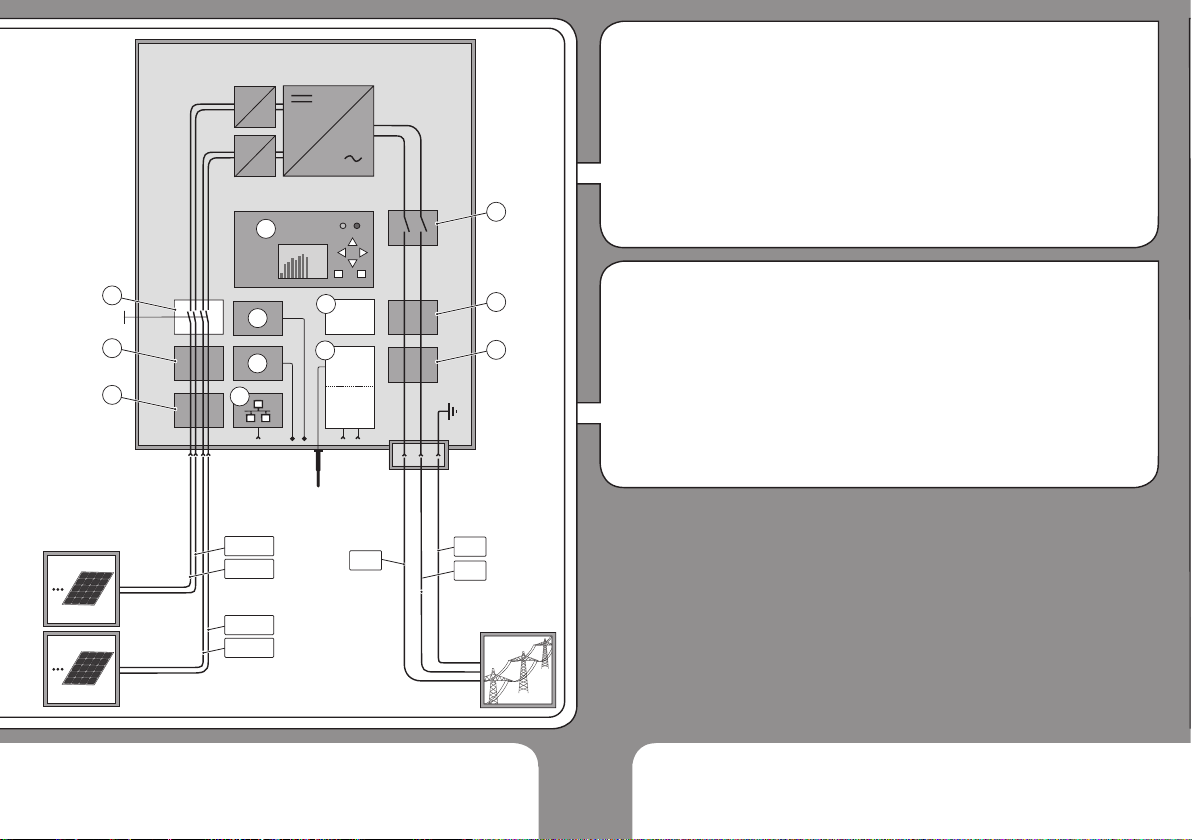
1. DC-side surge voltage protection
2. DC-side insulation monitoring
3. DC-side disconnection switch
4. Display, status LEDs, buttons
5. AC-side disconnection relay
6. Grid monitoring
7. AC-side surge voltage protection
8. Digital output port
9. Digital input port
10. Ethernet interface
11. SD card slot
12. WiFi or RS485 interface.
Note: The inverter is equipped
with either WiFi or RS485
communication.
Inverter Function EN
1. Protezione dalla sovratensione
lato DC
2. Monitoraggio dell’isolamento lato DC
3. Sezionatore lato DC
4. Display, LED di stato, tasti
funzione
5. Relè per disconnesione rete AC
6. Monitoraggio di rete
7. Protezione dalla sovratensione
lato AC
8. Uscita digitale
9. Ingresso digitale
10. Interfaccia: WLAN /
Ethernet
11. Slot per scheda SD
12. WLan o interfaccia RS485
Attenzione: L’inverter è dotato di
WLan o di RS485.
Funzionamento dell’inverter IT
This manual suits for next models
3
Table of contents
Other Peimar Inverter manuals


