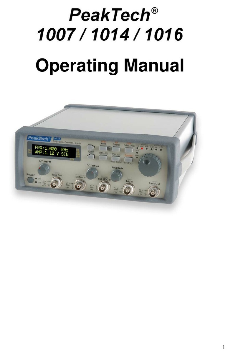
PeakTech 1015 GPIB User manual

i
Operation Manual
Programmable Function Generator
PeakTech®1015 GPIB
PeakTech®- Spitzentechnologie, die überzeugt

ii
Programmable Function Generator

iii
EC Declaration of Conformity
This is to certify that this equipment conforms to the protection requirements of the council directive
89/336/EEC, in the approximation of laws of the member states relating to Electromagnetic compatibility
and 73/23/EEC, The Low Voltage Directive by application of the following standards:
EN 50081-1 1992 Emissions Standard
EN 50082-1 1992 Immunity Standard
To ensure conformity with these standards, this instrument must be operated in accordance with the
instructions and specifications given in this manual.
CAUTION:
Even though this instrument complies with the immunity standards, the accuracy can be affected by
strong radio emissions not covered in the above standards. Sources such as hand held radio
transceivers, radio, and TV transmitters, vehicle radios and cellular phones generate electromagnetic
radiation that could be induced into the test leads of this instrument. Care should be taken to avoid such
situations or alternatively, check to make sure that the instrument is not being influenced by these
emissions.
GENERAL GUIDELINES
ALWAYS
Test this equipment before using to ensure proper operation.
Inspect the test leads before using to make sure there are no breaks or shorts.
Double-check all connections before testing.
Have some check on you periodically if working alone.
Have a complete understanding of the circuit being measured.
Disconnect power to the circuit, and then connect the test leads to the equipment, then to the circuit
being measured.
Never
Attempt to measure unknown high voltages.
Attempt to measure current with the meter in parallel to the circuit.
Connect the test leads to a live circuit before setting up the instrument.
Touch any exposed metal part of the test lead assembly.

iv
Safety Regulations
1. Do not touch any part of high voltage circuit or make any unnecessary high voltage
measurements. Do not remove the top or bottom covers of this unit unless you are a qualified
service person. Remove the power from this unit before removing the top and bottom covers.
2. When servicing this unit, the work area should be free from any electrical hazards. The floor
and workbench where the unit is operated should be insulated and free from any exposed
high voltage conductors. Remove any source of water or other conductive liquids in the
working area.
3. Connect this unit only to a 3-prong AC outlet, which conforms to electrical safety, codes. Do
not use any adapters to connect this unit to an AC receptacle.
4. Before operating or servicing this instrument, read the instruction manual and fully
understand the operating procedures. If you are servicing the unit, check the circuit you are
testing for high voltage.
5. Do not use this device in a room alone; be sure there are other people in the vicinity of your
work area in case of an emergency arises. Have emergency telephone numbers posted in
the work area in case a quick response is necessary.

v
Contents
Chapter 1. General specification
1. Product summary .......................................................................1
2. General specifications................................................................1
3. Electrical specifications ..............................................................2
4. Accessories................................................................................3
Chapter 2. Installation of the equipment
1. Initial inspection..........................................................................3
2. Preparation for use.....................................................................4
3. Environmental ............................................................................4
Chapter 3. Product description
1. Front Panel buttons and connectors description........................4
2. Rear panel..................................................................................6
Chapter 4. LCD, Front panel buttons and menus description
1. LCD display description..............................................................8
2. Menu description......................................................................11
3. Rotary Dial ...............................................................................14
4. Quick Reference Guide............................................................15
Chapter 5. Using this instrument
1. Equipment Needed...................................................................16
2. Preliminary setup......................................................................16
3. How to use the function wave generator..................................16
4. Generating a pulse waveform ..................................................18
5. Using the SWEEP waveform generator ...................................20
6. TTL output function ..................................................................21
7. VCF input function....................................................................21
8. RS232C Interface.....................................................................21
Chapter 6. Maintenance
1. Fuse Replacement ...................................................................23
2. Cleaning your instrument .........................................................23
Chapter 7. GPIB and RS-232C Interface
Safety Regulations .......................................................................23
General Instructions .....................................................................24
1. RS-232C Overview...................................................................25
2. RS-232C Communication.........................................................25
3. GPIB (IEEE-488.2) Overview...................................................26
4. GPIB Port .................................................................................26
5. Status and Event Registers......................................................27
6. Command Set ..........................................................................28
7. Command or Query message teminator ..................................29

Chapter 1. General specification
1. Product summary
This programmable function generator is one of a series of programmable test instruments that has
enhanced features over similar type of test instruments on the market today. This instrument features:
1. Output frequency range: 1Hz to 15MHz.
2. Waveforms: Sine, Triangle, Rectangular, RAMP and Pulse waveforms
3. DC Offset: -7.5V to +7.5V (no load).
4. Plots a Trend Graph on the LCD.
5. Digitally Synthesized for a stable output
6. Settings and functions may be selected and stored in memory from the front panel. Eight setups
may be stored in memory.
7. Function and ranges may be controlled from a PC via the RS232 or the optional GP-IB interface.
8. May be used with any line voltages from 85V to 270V AC may be used with out any internal
changes.
9. Low Distortion
2. General specifications
1. AC line and fuse rating:
Rated voltage Fuse Power consumption (max)
85 V to 270 V AC(±10%, 48 to 66Hz) T2AL/250V 15W
2. Operating Temperature:
0°C to +40°C (+32°F to +104°F) at a relative humidity 85% or less
3. Storage Temperature:
-20°C to +70°C (-4°F to +158°F) with a relative humidity of 85% less
4. Dimensions:
235 (width) x 296 (depth) x 85 (height) mm
4. Weight: about 1,5 kg
SAFETY CONSIDERATIONS
WARNING: Please follow manufacturers test procedures
whenever possible. Do not attempt to measure unknown
voltages or components until a complete understanding of the
circuit is obtained.
1

2
INTERNATIONAL SYMBOLS
DANGEROUS VOLTAGE
AC (ALTERNATING CURRENT)
DC (DIRECT CURRENT)
REFER TO INSTRUCTION MANUAL
GROUND
FUSE
DOUBLE INSULATION
BOTH DIRECT AND ALTERNATING CURRENT
3. Electrical Specifications
Note: Electrical specifications are at 25°C.
1) Frequency characteristics
* Freq. Range: 1Hz to 15MHz.
* Resolution: 4 digits
* Accuracy: ± (Set Value * 0.5% + 1 digit)
2) Output characteristics
* Output wave forms: Sine, Triangle, Square, TTL rectangular, Pulse, Step, etc.
* Output range: Max. 20 Vpp (No load); Max.10 Vpp into 50 Ω
* Impedance: 50 Ω± 5%
* Attenuator: 0 dB, 20 dB
* DC Offset: ±7.5 V DC (No Load)
3) Wave form characteristics
(1) Sine wave:
* Frequency range: 1 Hz to 15 MHz
* Amplitude: Max.10 Vpp (into an Impedance 50 Ω)
* Distortion: <1.5% (10Hz to 100kHz)
(2) Triangle wave:
* Frequency range: 1 Hz to 100 kHz
* Linearity: 1%
(3) Square wave
* Frequency range: 1 Hz to 15 MHz
* Rise and Fall times: < 35 nS (Maximum output)
* Symmetry: 20% to 80%
4) SWEEP characteristics
* SWEEP period: 9.95 S to 0.05 S
* SWEEP range: 1:1 to 10:1
* External SWEEP is controlled by the VCF input.

3
5) VCF input
* VCF accuracy: 1%
* Input voltage ±5 V DC, maximum sweep occurs at 5 V DC
* VCF input impedance: approx. 1 kΩ
6) TTL output: To 20 TTL/CMOS DRIVES
* Level(TTL): Fixed amplitude, < 0.4 V: for a low “L”, and g> than 2.4 V: for a
high “H”
7) FUNC output
* Level (TTL): Variable Amplitude (Max. 10 Vpp, Impedance 50 Ω)
4. Accessories
This unit is shipped with the following accessories:
1) Manual ··························································································1 copy
2) BNC cable ·······················································································1 unit
3) Line Cord·························································································1 unit
4) Spare fuse (T2AL/250V) ·································································1 unit
5) RS232 Cable (9Pin to 9Pin) ····························································1 unit
6) RS232 Program ··············································································1 unit
7) GP-IB port ·······················································································1 unit
Note:
The accessories may be changed to improve the product quality without notifying the customers.
Optional accessories will be made available at a later date.
IEC 1010 Over Voltage:
CATⅡ-1000V
Pollution Degree 2
WARNING: Use only correct size, voltage, and current rated fuses.
Test leads: Inspect the test leads for damaged insulation or exposed metal.
Check test lead continuity. Damaged leads should be replaced.
Chapter 2. Installation of the equipment
This chapter supplies all the necessary information to install this equipment. It includes: initial inspection,
preparation for use, appropriate voltage selection, packing for the return, etc.
1. Initial inspection
1) When received, inspect the shipping box for damage. If the shipping carton is damaged verify that
there is no mechanical damage to the instrument and it is functional. Verify that all accessories are
present.
2) Save the shipping carton and packing material until the unit is verified functional and within
specification.
3) If the unit is not functional or accessories are missing, report all problems to the vendor where the
unit was purchased as soon as possible to arrange for repair or replacement.

4
4) Report any shipping damaged to the shipping carrier’s agent.
2. Preparation for use
1) Before tuning the unit on verify that the AC line is within 85 V to 270 V AC (±10%), at a line
frequency of 48 to 66 Hz.
2) Check to see if the fuse has the correct rating. (T2AL / 250 V)
3) Make sure the unit is connected properly and is being used within the specifications listed above.
3. Environmental
1) This equipment should be operated in a well-ventilated area, with in a temperature range of 0 to
+40°C (+32°F to 104°F) and a relative humidity 85% or less and stored in a dry place within
temperature range between -20°C to +70°C (-4°F to +158°F) with a relative humidity 85% less.
Chapter 3. Product description
In this chapter, the front and rear panel buttons, controls and connectors are described.
1. Front Panel buttons and connectors description
Programmable Function Generator
[Figure-1] Front Panel
1) VCF input terminal
An external voltage applied to this input causes the frequency to deviate. A + 5 Voltage applied to
the input causes a maximum frequency deviation and a –5 Volts a minimum frequency deviation.
The maximum deviation is 100:1 which is useful for external sweep and FM modulation.
2) TTL output terminal
A TTL signal level with the same frequency as displayed on the LCD is available from this terminal.
3) FUNC output terminal
The output waveform with the characteristics (amplitude, offset, etc) as displayed on the LCD is
available from this terminal
PeakTech®1015 GPIB

5
4) Rotary dial
The rotary dial when turned moves the cursor position on the LCD between the menu items and is
used to select waveforms, set the output amplitude, symmetry, frequency and offset values. It is
also used to set the sweep rate and width and edit the setup menu.
5) [FRQ] Button
This Button when pressed moves the cursor to indicate the frequency value.
6) Button
(1) Toggles the cursor between the selection mode cursor displayed as a (< or >) symbol and the
edit mode cursor displayed as a (◄or ►) symbol when changing waveforms, amplitude, offset
values or sweep settings on the display or in the setup menu.
(2) When the edit mode cursor is displayed (◄or ►) and numerical data is being edited, rotating the
rotary dial, changes the cursor symbol to a (gh) symbol indicating the digit selection mode and a
digit is highlighted. Pressing the Button again the cursor changes to a (v) symbol indicating
the digit edit cursor mode. Rotating the rotary dial changes the digit value.
7) [AMP] Button
Pressing this button moves the cursor to the waveform amplitude setting on the LCD
8) [EDIT] Button
Displays the cursor in the setup or Equipment menus for editing generator settings and data values.
9) [OFS] Button:
Moves the cursor to indicate the Offset voltage setting on the LCD.
10) [SYM] Button
Moves the cursor to indicate the waveform symmetry setting on the LCD.
11) [PWR] Button
Pressing this button for 1.5 to 2 second will turn the unit on. Pressing this button again for 1.5 to 2
seconds will turn the power off.
12) [F1, F2, F3, F4, F5] Buttons
These buttons have a corresponding menu item displayed on the LCD when the MENU buttons
are pressed. Pressing the F button selects the desired item.
13) [MENU] Button
Displays the MENU and submenus as shown in Figure 2. The menu is explained in detail in a later
chapter.
Table of contents
Other PeakTech Inverter manuals