Pavone Sistemi 1008 User manual

Pavone Sistemi
pesatura elettronica industriale
Pavone Sistemi
pesatura elettronica industriale
USER MANUAL
TESTER 1008 for checking simultaneously a weighing system with up to 4 load cells
Calibrator and mV/V signal simulator
Software version P28901

Page II

Rel ID 170504 SW 0.4
Page 1
INDEX
Technical Specifications ............................................................................... Page 2
Connection Sub-D 25 poles.......................................................................... Page 3
Tester: Switch ON ....................................................................................... Page 4
Signal Detection.......................................................................................... Page 5
Tester Functions........................................................................................... Page 6
Display ...................................................................................................... Page 7
Tester Functions........................................................................................... Page 8
Tester Functions: Autotare............................................................................. Page 10
Tester: Calibrator Functions........................................................................... Page 11-12
Main Menu ................................................................................................ Page 13-14
Instrument Files Menu .................................................................................. Page 15
Configuration Files Menu ............................................................................. Page 16
NFC Communication Files............................................................................ Page 17
Management from PC.................................................................................. Page 18
Example: Configuration Files ........................................................................ Page 18

Page 2
TECHNICAL SPECIFICATIONS
Power Supply: 4 x 1,5V Alkaline Batteries or NiMh 1.2V
rechargeables
Consuption: Max. 170 mA (Max. Light, 4 load cells of 350 Ohm)
Operating Temperature: -10°C ÷ +50°C
Storage Temperature: -20°C ÷ +70°C
Display: LCD graphic monochrom. 4” (240 x 128 pixels)
Keyboard: Touch panel + Swtich On button
Dimensions: 185 x 93 x 36 mm (H x L x D)
Case: Palm- ABS
Protection Degree: IP54
Load cells Conncetion: Sub-D 25 poles cable
4 indipendent channels:
Load Cells Excitation: 3.3 Vdc / 50 mA (max 4 load cells of 350 Ohm)
Internal Resolution: 24 bit
Weight Display: Up to 50.000 divisions
Input Signal: From -3.9 to 3.9 mV/V
Load Cells Impedence: From 350 Ohm to 2000 Ohm
Calibrator Specifications: For equipment with load cells excitation from +/-3Vdc
up to +/-15 Vdc with input resistance >100 kohm.
Output Signal: -3 mV /+20.3 mV (Optional +30mV)
Resolution: 16 bit
Output: Panel Touch
Linearity: < 0,02% FS
Temperature Drift: 0,001% FS / °C
Communication Ports: N° 1 USB device (connection to a PC)
N° 1 RS232 (connection to instrument)
N° 1 NFC (connection to DAT1400)
Status Battery: Battery Icon 5 levels
Auto Switch Off: Programmable
Microcontroller: ARM Cortex M0+ 32 bit, 256KB Flash on board from
USB
Setup Memory: 64 Kbytes.
Archive and Files Memory: 1024 Kbytes
Archive and Optional Files Memory: µSD card (not removable)
Complies with: EN61000-6-2, EN61000-6-3 for EMC; EN61010-1
Electrical Safety

Page 3
SUB-D 25 POLES CONNECTION

Page 4
TESTER SWITCH ON
The LC Tester1008 shows the following display for about 2 seconds where Firmware and Software
Rev. are displayed.
Then, select the number of load cells connected to the junction box mod. CGS4C -CEM4C (or other)
and confirm with “V” key.

Page 5
SIGNALS DETECTION
The LC Tester 1008 automatically detects the input impedance values of the load cells connected,
choosing among the 4 available values “ 350Ω, 700Ω, 1000Ω e 2000Ω”.
The detected values can all be changed if the load cell impedance is different from the 4 available
values.
Note: The impedance values result in a variation in the reading of the individual signals of each load
cell.
During impedence measurement the LC Tester 1008 displays :

Page 6
TESTER FUNCTIONS
The LC Tester 1008 allows the simultaneous display of the “mV / V” signal of each load cell, of the
weight “Kg ..gr..t..lb..N..KN”, of the percentage of the single load “ % FS “ and their distribution”% “.
Note: The parameters in the “Weighing Data” Menu handle the correct detection of the individual
weights displayed by the LC Tester 1008.
It also detects the integrity of the load cell and its electrical connections.
Any anomalies are indicated as follows: No Exc-, No Exc + and Signal.
The LC Tester 1008 has the “Peak” function. It detects “Kg ..gr..t..lb..N..KN” weight values ??and
their “mV / V” signals.
The detected peak values ??can be saved and displayed in the “HOLD” screen.
The LC Tester 1008 is equipped with the Autotare function resulting in the reset of the “Kg..gr..t..lb..N..
KN” weight values, load values ??”% FS” and distribution “%”.
The LC Tester 1008 can receive and transmit the weight display setup configuration for the mod.
DAT400, MC302, MCT1302 via serial and DAT1400 via NFC connection.
The LC Tester 1008 is also a mV / V signal simulator.
Page 7
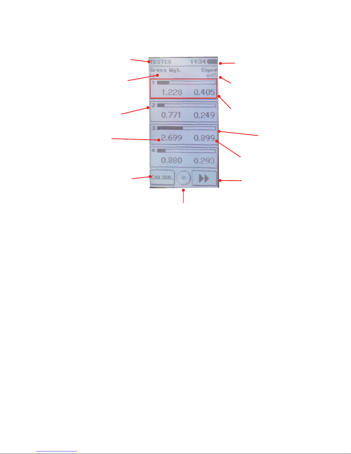
DISPLAY
Active Function Clock and Batteries Status
Heading (gross/net) and
measurement unit of the
below values. Heading and measurement unit
of the below values.
Load cell number LOAD CELL
Bar graph of the FS
value “kg..gr”
Weight value
Note: Set the parameter
in “Weighing Data Menu”
Access Menu Key
Signal value “mV/V”
Change function key TESTER /
CALIBRATOR. Change of Display Key
The displayed “squared boxes” depend on the number of load cells selected when powering on the
LC Tester 1008.
The change of the displayed values determines the display of the following alternative screens:

Page 8
TESTER FUNCTIONS
The following displays can be selected with the key: >>
Display of “Kg” load values and
“mV / V” signal values.
The displayed values are the
weight in Kg applied to each
load cell and its “mV / V” signal.
Pressing around “Gross Weight”
it activates the autotare function
and the display shows “Net
Weight”, resetting the weight
values, the load percentage and
the distribution percentage.
Pressing again it restores the
gross weight function.
Display of load percentage and
weight distribution percentage
The displayed values are the
load percentage applied to
each load cell their distribution
percentage.
Display of the load cells input
resistance.
The impedance of each load cell
is expressed in Ohm.
It is possible to manually change
each impedance value by cli-
cking directly on the value itself
and setting the new value. When
rebooting, the values calculated
by the LC Tester 1008 tester are
restored.
Table of contents


