Partner Tech International PT-6200 User manual
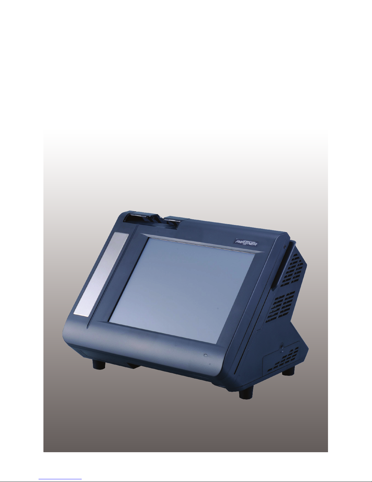
PT-6200
Service Manual


i
Copyright
This publication, including all photographs, illustrations and software, is protected under international
copyright laws, with all rights reserved. Neither this manual, nor any of the material contained herein, may be
reproduced without written consent of the author.
Disclaimer
The information in this document is subject to change without notice. The manufacturer makes no representa-
tions or warranties with respect to the contents hereof and specically disclaims any implied warranties of
merchantability or tness for any particular purpose. The manufacturer reserves the right to revise this publi-
cation and to make changes from time to time in the content hereof without obligation of the manufacturer to
notify any person of such revision or changes.
Trademark recognition
All product names used in this manual are the properties of their respective owners and are acknowledged.
Federal Communications Commission (FCC)
This equipment has been tested and found to comply with the limits for a Class A digital device, pursuant to
Part 15 of the FCC Rules. These limits are designed to provide reasonable protection against harmful interfer-
ence in a residential installation. This equipment generates, uses, and can radiate radio frequency energy
and, if not installed and used in accordance with the instructions, may cause harmful interference to radio
communications. However, there is no guarantee that interference will not occur in a particular installation. If
this equipment does cause harmful interference to radio or television reception, which can be determined by
turning the equipment off and on, the user is encouraged to try to correct the interference by one or more of
the following measures:
Reorient or relocate the receiving antenna.
Increase the separation between the equipment and the receiver.
Connect the equipment onto an outlet on a circuit different from that to which the receiver is connected.
Consult the dealer or an experienced radio/TV technician for help.
Shielded interconnect cables and a shielded AC power cable must be employed with this equipment to ensure
compliance with the pertinent RF emission limits governing this device. Changes or modications not ex-
pressly approved by the system’s manufacturer could void the user’s authority to operate the equipment.
Declaration of conformity
This device complies with part 15 of the FCC rules. Operation is subject to the following conditions:
This device may not cause harmful interference, and
This device must accept any interference received, including interference that may cause undesired operation.

ii
About this manual
The service manual provides service information for the PT-6200. This manual is designed to help train
service personnel to locate and x failing parts on the machine.
This manual consists of the following sections:
Chapter 1 Getting Started:
This section covers unpacking and checking the package contents, and identifying components.
Chapter 2 BIOS Setup Utility:
The BIOS chapter provides information on navigating and changing settings in the BIOS Setup
Utility.
Chapter 3 Installing Drivers and Software:
This chapter provides information on installing drivers for supported operating systems.
Chapter 4 Locating the Problem:
Refer to this chapter to locate the failing part or cause of the problem that requires servicing.
Chapter 5 Replacing Field Replaceable Units (FRUs):
This chapter provides drawings and instructions to replace all FRUs.
Appendix: Optional Components, Exploded Diagram, and Parts List:
The appendix includes an exploded diagram of the machine and the parts list and order number for
each part.
Safety information
Before servicing the machine, read the safety information under “Safety and precautions” on page 53.
Revision history
Version 1.0, May 2008

iii
TABLE OF CONTENTS
CHAPTER 1 GETTING STARTED................................................ 1
Unpacking the machine .................................................................................1
Identifying components .................................................................................2
CHAPTER 2 BIOS SETUP............................................................ 5
About the Setup Utility ...................................................................................5
Entering the Setup Utility ..........................................................................6
BIOS navigation keys ................................................................................6
Using BIOS ...............................................................................................7
Standard CMOS features...............................................................................8
Advanced BIOS Features ............................................................................10
Advanced Chipset Features.........................................................................12
Integrated Peripherals..................................................................................14
►OnChip IDE Device .............................................................................15
►OnChip PCI Device .............................................................................16
►SuperIO Device...................................................................................17
Power Management Setup...........................................................................18
PnP/PCI Congurations ...............................................................................20
► IRQ Resources....................................................................................21
PC Health Status..........................................................................................22
Frequency/Voltage Control...........................................................................23
Other BIOS Options .....................................................................................24
CHAPTER 3 INSTALLING DRIVERS AND SOFTWARE............ 27
Driver auto installation..................................................................................27
Intel Chipset Driver.......................................................................................28
Intel Chipset Graphics Driver .......................................................................30
Audio driver..................................................................................................32
LAN Driver....................................................................................................34
Touch Screen Driver.....................................................................................36
Calibrating the touchscreen .....................................................................39
CHAPTER 4 LOCATING THE PROBLEM .................................. 41
General checkout guidelines........................................................................41
Cash drawer checkout .................................................................................41
LCD symptoms.............................................................................................42
Touch screen symptoms ..............................................................................43

iv
Power symptoms..........................................................................................43
Network symptoms.......................................................................................43
USB symptoms ............................................................................................44
Peripheral-device symptoms........................................................................44
Boot symptoms ............................................................................................44
Mainboard jumper settings...........................................................................45
Setting a jumper...........................................................................................45
Mainboard jumpers ......................................................................................46
Mainboard connectors..................................................................................47
Inverter connectors ......................................................................................48
CHAPTER 5 REPLACING FIELD REPLACEABLE UNITS (FRUs)
..................................................................................................... 49
Safety and precautions ................................................................................49
Before you begin..........................................................................................50
Replacing parts ............................................................................................50
Front Panel...................................................................................................51
MSR .............................................................................................................51
Mainboard ....................................................................................................52
Hard drive.....................................................................................................53
Thermal Printer ............................................................................................54
Customer Display.........................................................................................55
Speaker........................................................................................................55
LCD Panel....................................................................................................56
Inverter.........................................................................................................56
Touch Panel .................................................................................................57
Memory ........................................................................................................57
Battery..........................................................................................................57
APPENDIX PART LIST AND SPECIFICATION........................... 59
Part list for White PT-6200 ..........................................................................60
Part list for Charcoal PT-6200 .....................................................................61
Specications...............................................................................................62

v
LIST OF FIGURES
Figure 1.1 Unpacking the machine ......................................................... 1
Figure 1.2 Front-right view of the machine.............................................. 2
Figure 1.3 Rear view............................................................................... 3
Figure 1.4 PT-6200 I/O connectors ......................................................... 4
Figure 3.1 Main BIOS menu.................................................................... 6
Figure 3.2 Standard CMOS Features menu ........................................... 8
Figure 3.3 IDE Primary Master submenu................................................ 9
Figure 3.4 Advanced BIOS Features menu .......................................... 10
Figure 3.5 Advanced Chipset Features menu....................................... 12
Figure 3.6 Integrated Peripherals menu................................................ 14
Figure 3.7 VIA OnChip IDE Device submenu ....................................... 15
Figure 3.8 VIA OnChip PCI Device submenu ....................................... 16
Figure 3.9 SuperIO Device submenu.................................................... 17
Figure 3.10 Power Management Setup menu ...................................... 18
Figure 3.11 PnP/PCI Conguration menu ............................................. 20
Figure 3.12 IRQ Resources submenu................................................... 21
Figure 3.13 PC Health Status menu ..................................................... 22
Figure 3.14 PC Health Status menu ..................................................... 23
Figure 4.1 Connecting a cash drawer ................................................... 42
Figure 4.2 PT-6200 mainboard jumpers................................................ 46
Figure 4.3 PT-6200 mainboard connectors........................................... 47
Figure 4.4 Inverter connectors .............................................................. 48
Figure 6.1 Exploded diagram main parts .............................................. 59
Figure 6.2 Exploded diagram MSR parts.............................................. 59

vi

1
CHAPTER 1
GETTING STARTED
This chapter describes how to unpack and identifying components on the device. The following topics are
described.
Unpacking the machine on page• 1
Identifying components on page• 2
Unpacking the machine
It is a good idea to save the packaging materials and shipping box in case that machine needs to be returned
for service. Please un-pack and re-pack the machine terminal as shown in Figure 1.1.
Figure 1.1 Unpacking the
machine
2 CHAPTER 1 GETTING STARTED
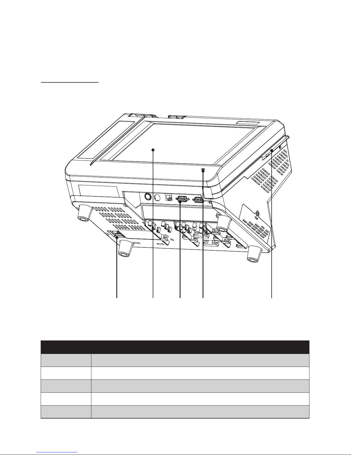
Identifying components
This section describes the parts and connectors on the machine.
Front-right view
1 52
Figure 1.2 Front-right view of the machine.
Component Description
1 Power Button
2 10.4-inch TFT LCD; 5-wire Resistive touch
3 IO Panel
4 LED Power Indicator
5 Tripple-track MSR
3 4
Table of contents
Other Partner Tech International Touch Terminal manuals


