Panoview Prefessional Cinema Motorized Screen User manual

Professional Cinema
Motorized Screen
Set-up Guide

2 | Motorized Screen Set-Up Guide
IMPORTANT SAFETY INSTRUCTIONS
Basic safety precautions, including the following should always be followed.
• Close supervision is necessary when any motorized screen is used by or
near children, do not leave motorized screen unattended while in use.
• Do not operate motorized screen with damaged cord or if the motorized
screen has been dropped or damaged, until it has been examined by a
qualified service technician.
• Position the cord so that it will not be tripped over, pulled or in contact with
hot surfaces.
• Never yank cord to pull plug form outlet. Always grasp plug by head and
pull to disconnect.
• Let appliance cool completely before putting away. Loop cord loosely
around appliance when storing.
• To reduce the risk of electric shock, do not immerse this motorized screen
in water or other liquids.
• To reduce the risk of electric shock, do not disassemble this appliance,
only a qualified service technician may service or repair motorized screen.
Incorrect reassemble can cause electric shock when the motorized screen
is used.
• Only use accessory attachment recommended by the manufacturer. Use
of non-manufacturer recommended accessory attachments, may void the
screens warranty and release Panoview of all liability.
• Basic electrical safety precautions should always be observed.
• In the event, the above mentioned safety precautions are not observed, the
warranty may be void and Panoview released of all liability.

Motorized Screen Set-Up Guide | 3
Thank you for choosing Panoview screens. All screens have passed the strict
quality inspection before delivery. Read this manual carefully to ensure proper
usage.
Important Attention: The installation of the screen, the electric wire
connection, the setting of the limit switches must be made by a trained
technician only.
SWITCH BOX
PLUG
Switch Jack(J3)
12V Trigger Jack(J4)
J4
Motorized screen with IR remote control, switch control & 12v trigger port.
Technical data:
Input Voltage: 120VAC/60HZ
Output Voltage: 3A
Fuse: 1A
IR Remote Control Distance: ≤8m, ±15°Horizontal
12V Trigger Jack: OD3.4xID1.3
12V Trigger Signal: Voltage:7---11VAC or 8---16VDC, Current: ≥2mA
IR Handset: 1pc
Switch control: 1pc

4 | Motorized Screen Set-Up Guide
INSTALLATION
Unpack screen carefully, be sure screen is in good condition and check that
all accessories are included inside carton.
Care in mounting and care in correct operation will mean a long and
satisfactory life for your Panoview screen. Locate the screen where the
audience can best see it and where other furnishings in the room permit.
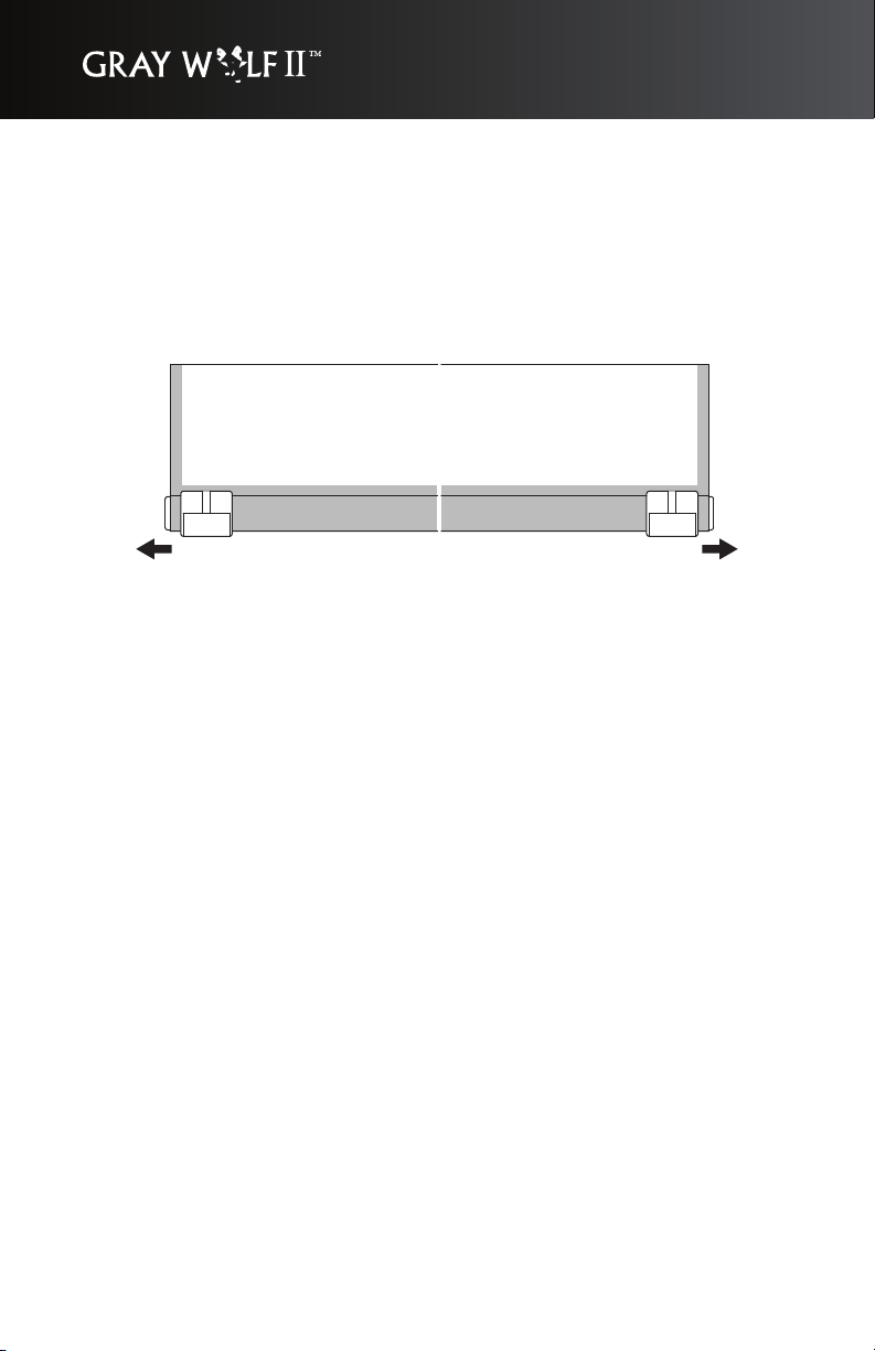
Remove two pulling locks on the bottom slat bar after the case has been
installed.
Refer the diagram below to mount screen to wall or ceiling.
L1
L2
40mm
SIZE(HxW)
1630x2130(4:3 100")
1930x2540(4:3 120")
1490x2130(16:9 92")
1700x2440(16:9 106")
1890x2760(16:9 120")
L1
2365mm
2775mm
2365mm
2675mm
2995mm
L2
2385mm
2795mm
2385mm
2695mm
3015mm

Motorized Screen Set-Up Guide | 5
ELECTRIC CONNECTION
Internal wiring has been completed at the factory. No additional wiring is
necessary.
Note: All wiring related to the screen, may only be serviced by a manufacturer
approved trained electrical technician. Tampering with electrical wiring may
void warranty and release Panoview of liability.
AC 120V/60Hz
END CAP
YELLOW/GREEN
PLUG
RED
BLACK
BLACK
BLACK
WHITE
BLACK
BLACK
WHITE
RED
MICRO SWITCH
CONNECT THE LINE PILLAR
MICRO SWITCH
BLACK(DOWN)
TRANSFORMER
RELAY(DOWN)
RELAY(UP)
FUSE
C250/R400
IC
J2
J1
J3
J4
IR MODULE
N
RED(UP)
MOTOR
MOTOR
C
M
G
BLUE
L
G
N
JACK4
J4
TO P1 RED
BLACK
SWITCH
BLUE
JACK3
J3
RED
BLACK
BLUE
6 | Motorized Screen Set-Up Guide
OPERATING INSTRUCTION:
Remove two pulling locks on the bottom bar first before any operation. this is
important to prevent motor damage.
Plug in power supply.
For Switch control: Plug in Switch into switch jack. Press button to Up
position, screen goes up. Press button to stop position, screen stops. Press
button to down position, screen goes down.
For IR Remote: Direct the handset to IR window on screen housing. Press
the Up/Stop/Down button on the hand set, screen goes Up/Stop/Down
accordingly.
For 12V trigger: Input 12V trigger signal, screen goes down. Stop this signal,
screen goes up.
Electric lock: Press the Up & Down buttons on the IR handset together, then
all Up & Down buttons on the switch and IR handset will be locked. To be
unlocked press
Stop button on the IR handset again or unplug the power supply and plug in
again.
Keep the screen rolled in its protective case when not in use. Always examine
both front and back of surface before re-rolling into case to make certain
screen is free of dust, dirt or other foreign matter.
Motorized Screen Set-Up Guide | 7
SCREEN ADJUSTMENT
Note: Adjustments to screen limit positions, can only be performed by a
trained technician.
Screen travel is stopped automatically in the down and up positions by limit
switches that are preset in the factory. If it Is necessary to adjust for more or
less, please follow the steps below for adjustment.
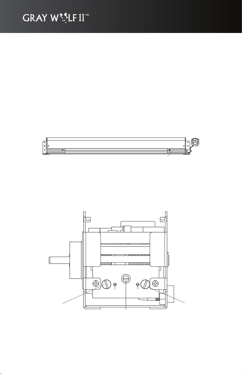
Disconnect the power supply first before any operation. Remove the plate on
right bottom side of screen housing.
PLATE
This is important.
Before the adjustment, loosen the fastening screw (F).
The upper limit switch is on the left side and the bottom limit switch is on the
right side.
After all the adjustments, tighten the fastening screw (F).
LEFT SCREW(LS) RIGHT SCREW(RS)
FASTEN SCREW(F)
FR
FL

8 | Motorized Screen Set-Up Guide
SETTING THE DOWN LIMIT POSITION
To reduce the screen drop:
Make sure middle fastening screw (F) is loosened, then loosen small right
fastening screw (FR), Turn right screw ( RS ) counterclockwise to decrease
the amount of screen drop. Run the screen down to test the stop position. If
the screen drops too far, adjust the limit switch again. Repeat until the desired
position is set. When completed, fasten the middle fastening screw (F) and
small right fastening screw (FR).
To increase the screen drop:
Make sure middle fastening screw (F) is loosened, then loosen the small right
fastening screw (FR). Turn the right screw (RS) clockwise to increase the
amount of screen drop. Run the screen down to test the stop position. If the
screen does not drop enough, adjust the limit switch again. Repeat until the
desired position is set. When completed, fasten the middle fastening screw
(F) and small right fastening screw (FR).

Motorized Screen Set-Up Guide | 9
SETTING THE UP LIMIT POSITION
CAUTION: Do not allow the slat bar to become wedged between the roller
and case. This could damage the fabric and motor. Always check that the slat
is free to move inside the case.
If the screen travels too far into the case:
Make sure the middle fastening screw (F) is loosened, then loosen the small
left fastening screw (FL). Turn the left screw (LS) clockwise to decrease the
amount of travel. Run the screen up to test the stop position. If the screen
does not stop properly, adjust the limit switch again. Repeat until the desired
position is set. When completed, fasten the middle fastening Screw (F) and
small left fastening screw (FL).
If the screen does not travel far enough into the case:
Make sure the middle fastening screw (F) is loosened, then loosen the small
left fastening screw (FL). Turn the left screw (LS) counterclockwise to increase
the amount of up travel. Run the screen up to test the stop position. If more
travel is desired, adjust the limit switch again. Repeat until the desired
position is set. When completed, fasten middle Fasten Screw (F) and small
left fasten screw (FL).

Optoma Technology, Inc.
715 Sycamore Drive, Milpitas CA 95035
Tel: 408-383-3700 • Fax:408-383-3702
For more information, please visit www.Optoma.com.
Specifications subject to change without notice. Copyright 2006 Optoma Technology, Inc.
USA
715 Sycamore Drive
Milpitas, CA 95035, USA
Tel: 408-383-3700
Fax: 408-383-3702
www.optomausa.com
5630 Kennedy Road
Mississauga, ON, L4Z 2A9, Canada
Tel: 905-882-4228
Fax: 905-882-4229
www.optoma.com
Canada
Table of contents
Other Panoview Projection Screen manuals

Panoview
Panoview Panoview DS-9092PM User manual

Panoview
Panoview DP-MWxxxxA User manual

Panoview
Panoview Panoview DP-MW3084A User manual

Panoview
Panoview Panoview Graywolf II User manual

Panoview
Panoview DF-WW9xxxF User manual

Panoview
Panoview DS-9092PM User manual

Panoview
Panoview WhiteWolf DF-WW9106F User manual
Popular Projection Screen manuals by other brands

FART PRODUKT
FART PRODUKT Standard SCREEN Installation instruction

Draper
Draper E Series Installation & operating instructions

Elite Screens
Elite Screens Elite Tripod Series user guide

Laarhoven
Laarhoven Companion II General assembly instructions

Renogy
Renogy RMS-LFPS-US manual

Da-Lite
Da-Lite ExecutiveElectrol Instruction book


