Palstar AT5K User manual
© Copyright 2005– 2009 Palstar Inc.
Printed in the U.S.A.
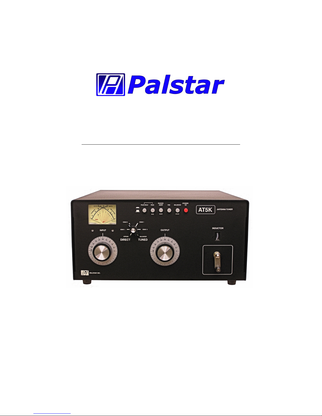
AT5K 3500 Watt Antenna Tuner
Owner’s Manual

WARNING: TO PREVENT FIRE OR
ELECTRICAL SHOCK DO NOT
EXPOSE TO RAIN OR MOISTURE
1. Read Instructions—All the safet and
operating instructions should be read before
the appliance is operated.
2. Retain Instructions—The safet and
operating instructions should be retained for
future reference.
3. Heed Warnings—All warnings on the
appliance should be adhered to.
4. Follow Instructions—All operating and
use instructions should be followed.
5. Cleaning—Unplug this appliance from the
wall outlet before cleaning. Do not use liquid
cleaners or aerosol cleaners. Use a damp
cloth for cleaning.
6. Do Not Use ttachments—not recom-
mended b the manufacturer or the ma
cause hazards.
7. Water and Moisture—Do not use this
product near water—for example, near a
bathtub, wash bowl, kitchen sink, laundr tub,
in a wet basement, or near a swimming pool—
and the like.
8. ccessories—Do not place this product on
an unstable cart, stand, tripod, bracket, or
table. The product ma fall, causing serious
injur to a child or adult, and serious damage
to the appliance.
9. Ventilation—This product should never be
placed near or over a radiator or heat register.
This product should not be placed in a built-in
installation such as a bookcase or rack unless
proper ventilation is provided or the manufac-
turer’s instructions have been adhered to. An
slots or openings in the cabinet are provided
for ventilation. To ensure reliable operation of
the video product and to protect it from over-
heating, these openings must not be blocked
or covered. The openings should never be
blocked b placing the product on a bed, sofa,
rug, or other similar surface.
10. Grounding or Polarization—this product
is equipped with a 3-wire line cord receptacle.
It is intended for use with a 3-wire properl
grounded power socket. Do not defeat the
safet purpose of the supplied line cord and
plug.
11. Power Sources—This product should be
operated onl from the t pe of power source
indicated on the marketing label. If ou are not
sure of the t pe of power supplied to our
home, consult our appliance dealer or local
power compan .
12. Power-cord Protection—Power-suppl
cords should be routed so the are not likel
to be walked on or pinched b items placed
upon or against them. Pa particular attention
to cords at plugs, convenience receptacles,
and the point where the exit.
13. Lightning—For added protection for this
product during a lightning storm, or when it is
left unattended and unused for long periods of
time, unplug it from the wall outlet.
WARNING: TO REDUCE THE RISK OF FIRE OR ELECTRIC SHOCK, DO NOT
EXPOSE THIS APPLIANCE TO RAIN OR MOISTURE. DO NOT
OPEN THE CABINET WHILE OPERATING. REFER SERVICING TO
QUALIFIED PERSONNEL ONLY.
CAUTION: TO PREVENT ELECTRIC SHOCK, DO NOT USE THE THREE WIRE
CORD WITH AN EXTENSION CORD RECEPTIACLE OR OTHER
OUTLET UNLESS THE BLADES CAN BE FULLY INSERTED TO
PREVENT BLADE EXPOSURE.
An appliance and cart combination should
be moved with care. Quick stops, exces-
sive force and uneven surfaces ma cause
the appliance and cart combination to
overturn.
The lightning flash with arrow head
s mbol, within an equilateral triangle, is
intended to alert the user to the presence
of uninsulated “dangerous voltage” within
the product’s enclosure that ma be of
sufficient magnitude to constitute a risk of
electric shock to persons.
The exclamation point within an equilateral
triangle is intended to alert the user to the
presence of important operating and
maintenance (servicing) instructions in the
literature accompan ing the appliance.
1-800-773-7931 WWW.PALST AR.COM
2 Important Safeguards

1-800-773-7931 WWW.PALST AR.COM
14. Power Lines—An outside antenna s s-
tem should not be located in the vicinit of
overhead power lines, other electric light or
power circuits, where it can fall into such
power lines or circuits. When installing an
outside antenna s stem, extreme care should
be taken to keep from touching such power
lines or circuits as contact with them ma be
fatal.
15. Overloading—Do not overload wall out-
lets and extension cords as this can result in a
risk of fire or electric shock.
16. Object and Liquid Entry—Never push
objects of an kind into this product through
openings as the ma touch dangerous volt-
age points or short-out parts that could result
in a fire or electric shock. Never spill liquid of
an kind on the product.
17. Servicing—Do not attempt to service this
product ourself as opening or removing
covers ma expose ou to dangerous voltage
or other hazards. Refer all servicing to quali-
fied service personnel.
18. Damage Requiring Service—Unplug this
product from the wall outlet and refer servicing
to qualified service personnel under the fol-
lowing conditions:
a. When the power-suppl cord or plug is
damaged.
b. If liquid has been spilled, or objects have
fallen into the product.
c. If the product has been exposed to rain or
water.
d. If the product does not operate normall b
following the operating instructions. Adjust
onl those controls that are covered b the
operating instructions. An improper adjust-
ment ma result in damage and will often
require extensive work b a qualified
technician to restore the product to its normal
operation.
e. If the product has been dropped or the
cabinet has been damaged.
f. When the product exhibits a distinct change
in performance—this indicates a need for
service.
19. Replacement Parts—when replacement
parts are required, be sure the service techni-
cian has used replacement parts specified b
the manufacturer or have the same character-
istics as the original parts. Unauthorized sub-
stitutes ma result in fire, electric shock or
other hazards.
20. Safety Checks—Upon completion of an
service or repairs to this product, ask the
service technician to perform safet checks to
determine that the product is in proper operat-
ing condition.
21. Outdoor ntenna Grounding—Before
attempting to install this product, be sure the
antenna or cable s stem is grounded so as to
provide some protection against voltage
surges and built-up static charges.
a. Use No.10 AWG copper, No.8AWG alumi-
num, No.17AWB copper-clad steel or bronze
wire or larger, as ground wire.
b. Secure antenna lead-in and ground wires to
house with stand-off insulators spaced from 4
feet to 6 feet apart.
c. Mount antenna discharge unit as close as
possible to where lead-in enters house.
d. A driven rod ma be used as the grounding
electrode where other t pes of electrode
s stems do not exist. Refer to the National
Electric Code, ANSI/NFPA 70-1990 for infor-
mation.
e. Use jumper wire not smaller than No.6
AWG copper or equivalent, when a separate
antenna grounding electrode is used.
Important Safeguards cont’d 3

4 Table of Contents
1-800-773-7931 WWW.PALST AR.COM
Important safeguards 2
Table of Contents 4
General Description 5
Installation 6
Rear Panel Connections 7
Front Panel Description 8
Schematic 10
Operating Your T5K 12
Specifications 15
Service and Warranty 16
Thank ou for purchasing a
Palstar AT5K Antenna Tuner.
This antenna tuner has been
designed and manufactured to
high qualit standards, and will
provide reliable operation for
man ears.
Please carefull read the
Owner’s Manual in order to take
advantage of the man interest-
ing features that will provide
ears of enjo able amateur
radio operation.

General Description 5
1-800-773-7931 WWW.PALST AR.COM
The Palstar AT5K Antenna
Tuner is an American made im-
pedance matching network that
can provide unbalanced and
balanced output with a power
rating of 3500 watts (single tone
continuous) and 5000 watts
PEP at certain Z ranges (p.14).
The AT5K T-matching network
utilizes a 1:1 unbalanced to bal-
anced transformer in the input of
the network. When the network
is properl tuned, a 50 Ohm im-
pedance will be presented to
both the input and output of the
balun for maximum efficienc .
The AT5K optimizes the per-
formance of our antenna and
transmitter b providing adjust-
able impedance matching using
a T-t pe circuit configuration.
The AT5K also measures the
power and Voltage Standing
Wave Ratio (VSWR) which al-
lows ou to tune the SWR to the
lowest ratio for the selected
transmission frequenc .
Integrated into the AT5K is a
frequenc -compensated lighted-
dial dual-movement SWR me-
ter. The meter features the abil-
it to read True Active Peak and
Peak Hold.
Designed to handle both Bal-
anced line feeds and Coax
feeds the AT5K features a front
panel mounted switch to select
between feeds.
Tuning is achieved with the front
panel mounted controls. The
Vernier capacitor dials allow for
tuning with precision and accu-
rac , while the Inductor crank
handle facilitates coarse adjust-
ments.

W RNING: Balanced antennas will produce high
RF voltages at the output post connectors. RF
burns may result if touched during transmission.
6 Installation
1-800-773-7931 WWW.PALST AR.COM
Unpacking
Carefull remove the AT5K from the shipping carton and inspect
it for signs of damage. If an damage is apparent, notif the trans-
portation carrier or dealer immediatel . We recommend keeping
the packing carton for moving, storing or reshipping the tuner
to us for repair if required.
Location
Select a location for the AT5K that allows the connectors to be
free from an possible contact with people, pets, or objects during
operation and with unrestricted air flow for cooling.
Installation Procedures
Connect a coax cable from our transmitter to the RF INPUT
connector on the rear panel. Keep the cable as short as possible.
If ou use a linear amplifier, connect our transmitter to the linear
amplifier input and the linear amplifier output to the AT5K.
Connect coax cable from our antenna to the COAX 1 or COAX
2 connector on the rear panel. These connectors are either direct
from the transmitter or through the tuned circuit, de-pending on the
setting of the OUTPUT SELECTOR switch on the front panel.
For coax feed (unbalanced) the BALANCED/COAX switch on the
front panel must be in the OUT position. This grounds the lower
end of the roller inductor, allowing coax feed.
For a balanced feed antenna connect a balanced feed line to the
white BALANCED OUTPUT posts (back panel). Note that for bal-
anced operation, the BALANCED/COAX switch on the front panel
must be in the IN position, and an LED above the switch will light,
indicating balanced feed.
Connect a dumm load to the BYPASS connector using a coax
cable. This lets ou select the dumm load from the DIRECT/
TUNED mode switch. An antenna that does not require the use
of an antenna tuner ma be connected to the BYPASS connector,
if desired.

Rear anel Description 7
1-800-773-7931 WWW.PALST AR.COM
12 VDC INPUT (2.1
mm plug) for 12VDC
@ 500mA to power
the meteri g, lamp,
relay a d fa .
RF INPUT coaxial
co ector for i put
from tra smitter or
amplifier.
GROUND post/wi g ut
grou d co ector.
BALANCED OUTPUT two
ylo High Voltage post
co ectors for output to RF
bala ced twi -lead a te as.
Relay switched from fro t
pa el co trol.
COAX 2 coaxial co ector
for output to A te a Two.
COAX 1 coaxial co ector
for output to A te a O e.
BYPASS coaxial co ector for
output to dummy load or reso-
a t a te a. Bypasses tu er,
but meter circuits are o if
12VDC adaptor is co ected
to jack located o rear pa el.
FIGURE 1 REAR PANEL CONNECTORS

8 Front anel Description
1. POWER/SWR METER Dual needle meter displa s
FORWARD and REFLECTED power in watts. SWR
is measured where the two needles intersect on the
red scale.
2. PE K ND PE K/HOLD Active circuitr is used to
offer peak reading for SSB. This peak feature is
also translated to provide an approximate 2 second
hold at the peak level for eas viewing. NOTE: The
PEAK/HOLD will function onl if the PEAK button is
pressed in as well.
3. R NGE The power range is 300 watts on low and
3000 watts on high (push button in for high).
4. F N The IN position turns on the fan which cools the
internal components of the tuner when using a ser-
vice that requires constant carrier operation (for e.g.
AM or RTTY).
5. B L NCED/CO X Selects either coax feed or bal-
anced feed. A LED shows when balanced mode is
selected.
1 2 3
7 8 9 10
4 5 6

Front anel Description 9
6. POWER ON The IN position provides power for the
Peak and Peak Hold metering circuit, rela and
meter illumination.
7. INDUCTOR 28 µH continuousl variable ceramic
roller inductor driven b a crank handle. Coupled to
the crank handle is a gear-driven precision me-
chanical counter. (Max.= 0; Min. = 229)
8. OUTPUT Continuousl adjustable output capacitor.
Min. capacitance=0. Max capacitance = 100.
9. DIRECT-TUNED MODE SWITCH Six-position rotar
switch selects an output coaxial connector.
a. DIRECT BYP SS selects BYPASS COAX connec-
tor b passing the impedance matching circuit but
providing SWR, FORWARD and REFLECTED
power meter readings.
b. DIRECT CO X 1 selects COAX 1 connector b -
passing the tuner matching circuit but providing
SWR, FORWARD and REFLECTED meter read-
ings.
c. DIRECT CO X 2 selects COAX 2 connector b -
passing the tuner matching circuit but providing
SWR, FORWARD and REFLECTED meter read-
ings.
d. TUNED CO X 1 selects COAX 1 connector
through the impedance matching T circuit.
e. TUNED CO X 2 selects COAX 2 connector
through the impedance matching T circuit.
f. TUNED B L selects the END FED WIRE connec-
tor through the impedance matching circuit. For
balanced antennas, the balanced coax switch (5)
must be IN.
10. INPUT Continuousl adjustable input capacitor.
Min. capacitance = 0. Max = 100.

10 AT5K Schematic
Other manuals for AT5K
2
Table of contents
Other Palstar Tuner manuals

Palstar
Palstar AT4K User manual

Palstar
Palstar AT1500DT User manual

Palstar
Palstar AT1KM User manual

Palstar
Palstar BT1500A User manual

Palstar
Palstar AT2K User manual

Palstar
Palstar AT1500CV User manual

Palstar
Palstar AT5K User manual

Palstar
Palstar AT2KD User manual

Palstar
Palstar AT5K User manual

Palstar
Palstar AT5K-HP User manual


Popular Tuner manuals by other brands


MFJ
MFJ MFJ-928 instruction manual

NAD
NAD C 445 owner's manual

Sony
Sony ST-SA5ES operating instructions

Sirius Satellite Radio
Sirius Satellite Radio SC-FM1 user guide

Antique Automobile Radio
Antique Automobile Radio 283501B Installation and operating instructions

Monacor
Monacor PA-1200R instruction manual


